3D Printing and Product Design:
Toilet Paper Holders:
These two toilet paper holders were some of my first 3D designs and were also my first client based manufacturing products. They both had their own unique constraints and requirements, and taught me a lot about not only 3D modeling, but also designing part that interface with other parts.
Pacific Cycling and Triathlon TP Holder:
This was my first toilet paper holder, and it was for a family friends local business. Pacific Cycling and Triathlon (what used to be Pacific Swim Bike Run) needed a TP holder of their store bathroom. Their bathroom did not have a TP holder in the wall, and due to limited space, they didn't want to buy a standing TP holder. They did have a horizontal assist bar which I decided would be the best place for one to go. I sketched up a general design and then got to measuring. I measured the diameter of the bar, the distance from the wall, and the diameter of the TP tube as well as that Diameter of a full roll of toilet paper itself.
For my design, I went with a snap-on style holder. The top part snaps on and off of the assist bar with an easy amount of force, but stays on when in use. The bottom part that holds the roll is small enough in diameter to allow for easy roll rotation, but not too small that it might break. It also features a lip to prevent the roll from slipping off. Overall, the design functions very well and is still in use (since around summer 2018).
There are many things that I would change if I were to do it again. For one, the color sticks out like a sore thumb. I tried to make it look more appealing by alternating colors (which I think helped), but I would make it all grey or a more toned down color if I were to make another one. Also the logo isn't necessary, and I would probably not include it if I were to do it again to make it more professional (not to mention PSBR is not their name anymore). I also would have made it a little less bulky. While it is very sleek, It did take a lot of plastic to print, and could probably be slimmed down a considerable amount and still function well.
Household TP Holder:
After my mom posted the first holder on Facebook, she got a message from a friend who was in need of a custom holder. The design that they want was similar in that it would snap on an assist bar, but the bar was tilted, so it would need to be re designed, and there were much more of an aesthetic constraint. They wanted it to be more minimalistic and industrial (less ergonomic looking). I got a measurement of the bar diameter and started working.
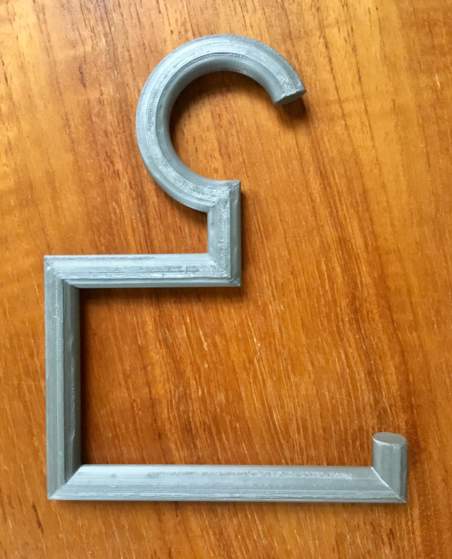
For this design, I went for a hanging style holder. Because of the slope, the TP holder would have to hang either at the top or bottom of the bar where it turned into the wall. Given this, I drew inspiration from a coat hanger. I sent multiple designs and revisions to my client and she gave me feedback until I came up with a good design. It was simple and when tested, it was effective.
If I were to do it again, I would have probably met with my client in person and seen the space I was working with as opposed to seeing it in photos or talking about it over the phone and through text. I feel that I would have came to a good design quicker, and would have better understood what my client wanted if I had done this.
Charger Lock - Spring 2018:
V1:
V2:
V3:
V4:
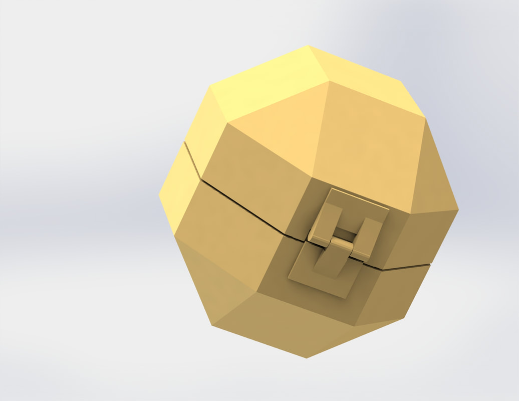
The charger lock was one of my first ideas that I made into a CAD model. The premise behind it is that family members (in my case, my sister) steal your phone charger and you never get it back. The lock goes over either the USB or the Lighting jack and can lock using an external lock like a pad lock. This way, no one will steal it because there it no way to open the lock and use it.
This design went through multiple iterations to refine the mechanism and design. I had yet to get into professional 3D modeling programs, so versions 1-3 were created using Autodesk Tinkercad. Version 4 was made using Fusion 360. There was a lot of learning and trial and error while making this design as it was in actuality my first real 3D design. I sometimes like to think of versions 1-3 as the actual charger lock concept design, whereas version 4 is an idea that was inspired after the fact and doesn't really contribute to the progression as it is an entirely new design (and doesn't even lock).
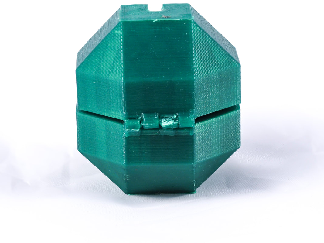
The first design started as a drawing on paper, and was quickly transferred into CAD. I didn't know much about tolerances and I was just going for a rough prototype. When I printed it, you can see that the hinge was too small and fused together, however the charger did fit into the lock as intended which was a success.
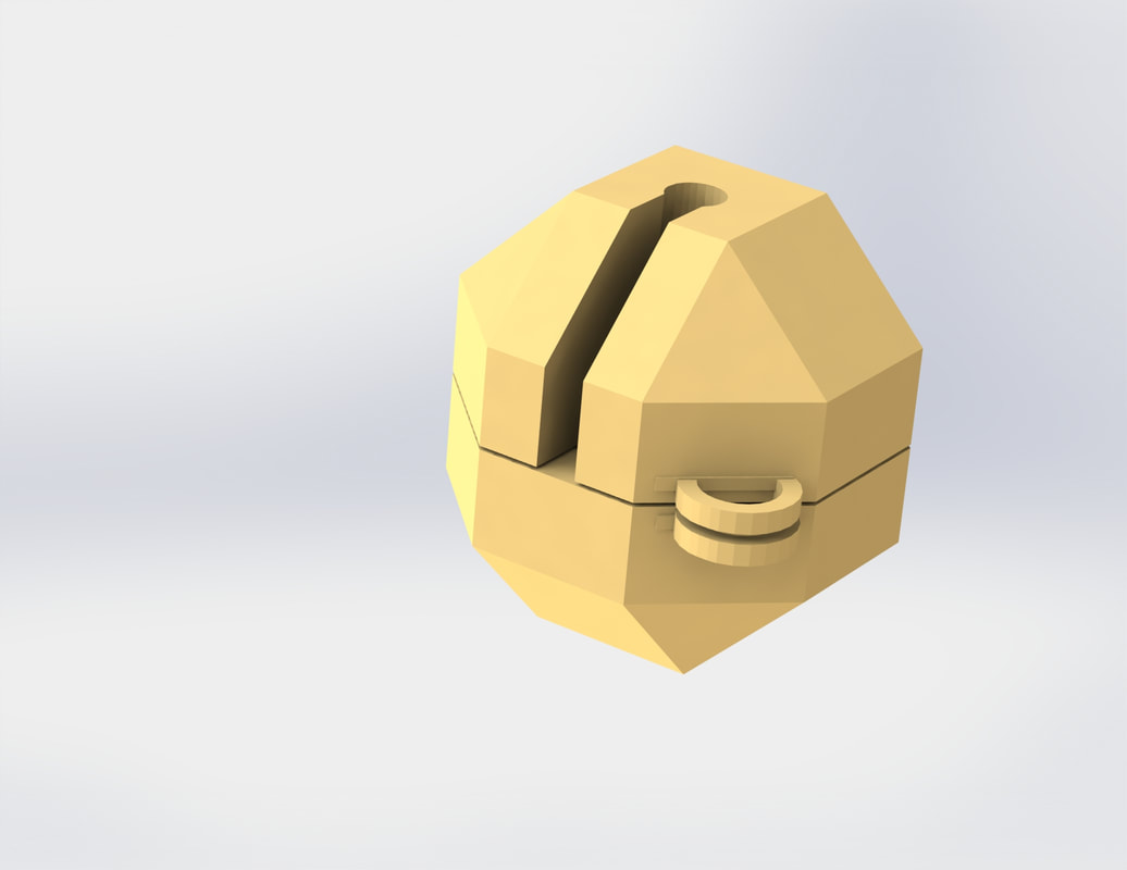
The second design Improved on the first in that I re-designed the hinge, and altered the locking mechanism. The newly printed part worked well although there was still a need for improvement. While the hinge did work this time, it was too fragile and broke within a couple minutes of me playing with it. Also, While the locking mechanism looked better, and functioned better (in theory) than the previous design, It was also too fragile because of the material I was working with (PLA).
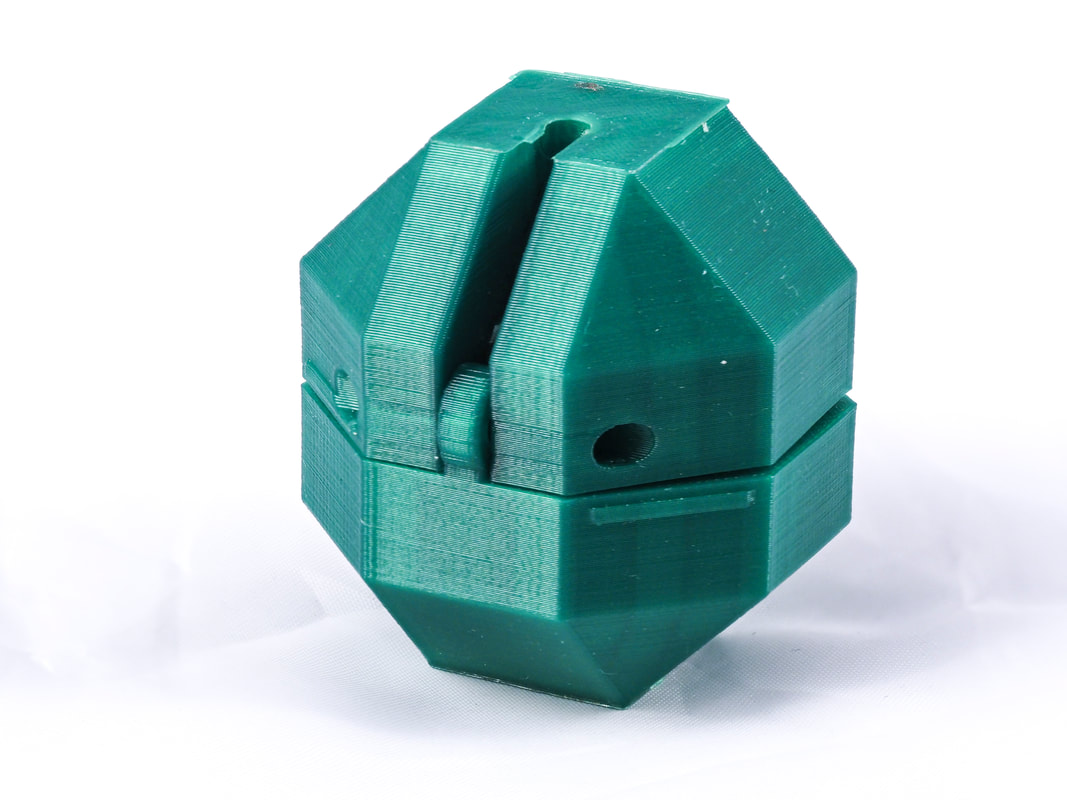
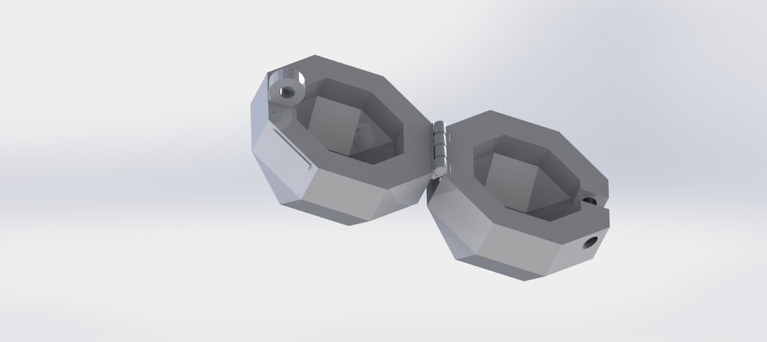
The third design is in a way only a test of the hinge itself. I couldn't figure out how to re-design the hinge from version 2, so I just redesigned it from version 1 (this was due to my lack of CAD Knowledge at the time). Ultimately the locking design in version 2 was the better design IMO, and would not break if reinforced and made with stronger plastic or metal (if this were to be a product brought to market). I worked meticulously to design the hinge in this version. I used a door hinge as a visual reference, and in the end produced a design that functioned well and didn't break when printed.
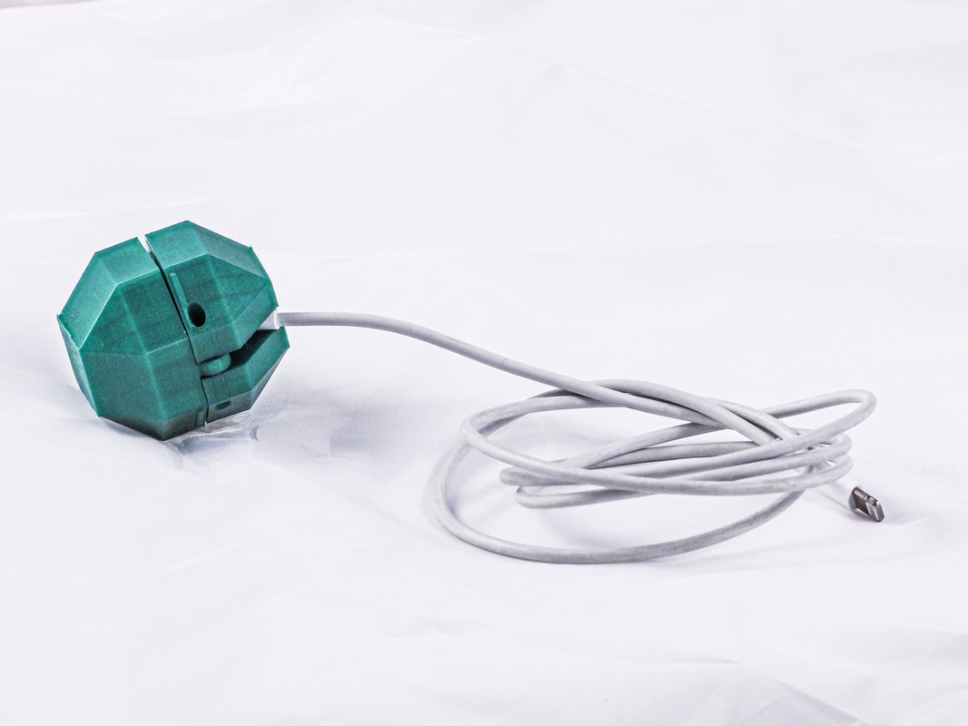
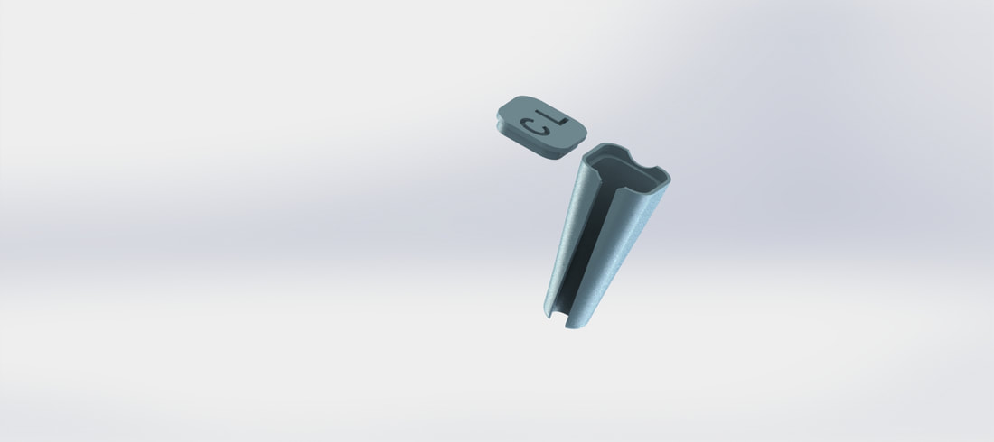
The fourth design as previously stated is more inspired buy the other three designs that a continuation of the design. I noticed that the other designs were very bulky and wanted to make a more simpler smaller re design. I made this in two parts, and utilized my measurements and lofts to create a design that worked well as an endcap to the charger. This currently functions as a cap that protects the end of the charger, and does a very good job at it, and is very small, so it doesn't take up too much space.
Overall, the experience taught me a lot. It was my first real CAD design, so It got me familiar with 3D modeling, designing parts to fit together, and the design-test-re-design process.
If I were to do it again (which I do plan on), I would probably work off the smaller design (V4). This design is smaller, more streamline, and fits together better than the other designs. With my current experience, I would be able to design the lock closer to my vision, and would be able to make it work better. I always wanted to make it work with an integrated number lock, and Future designs might feature this.
This design went through multiple iterations to refine the mechanism and design. I had yet to get into professional 3D modeling programs, so versions 1-3 were created using Autodesk Tinkercad. Version 4 was made using Fusion 360. There was a lot of learning and trial and error while making this design as it was in actuality my first real 3D design. I sometimes like to think of versions 1-3 as the actual charger lock concept design, whereas version 4 is an idea that was inspired after the fact and doesn't really contribute to the progression as it is an entirely new design (and doesn't even lock).
The first design started as a drawing on paper, and was quickly transferred into CAD. I didn't know much about tolerances and I was just going for a rough prototype. When I printed it, you can see that the hinge was too small and fused together, however the charger did fit into the lock as intended which was a success.
The second design Improved on the first in that I re-designed the hinge, and altered the locking mechanism. The newly printed part worked well although there was still a need for improvement. While the hinge did work this time, it was too fragile and broke within a couple minutes of me playing with it. Also, While the locking mechanism looked better, and functioned better (in theory) than the previous design, It was also too fragile because of the material I was working with (PLA).
The third design is in a way only a test of the hinge itself. I couldn't figure out how to re-design the hinge from version 2, so I just redesigned it from version 1 (this was due to my lack of CAD Knowledge at the time). Ultimately the locking design in version 2 was the better design IMO, and would not break if reinforced and made with stronger plastic or metal (if this were to be a product brought to market). I worked meticulously to design the hinge in this version. I used a door hinge as a visual reference, and in the end produced a design that functioned well and didn't break when printed.
The fourth design as previously stated is more inspired buy the other three designs that a continuation of the design. I noticed that the other designs were very bulky and wanted to make a more simpler smaller re design. I made this in two parts, and utilized my measurements and lofts to create a design that worked well as an endcap to the charger. This currently functions as a cap that protects the end of the charger, and does a very good job at it, and is very small, so it doesn't take up too much space.
Overall, the experience taught me a lot. It was my first real CAD design, so It got me familiar with 3D modeling, designing parts to fit together, and the design-test-re-design process.
If I were to do it again (which I do plan on), I would probably work off the smaller design (V4). This design is smaller, more streamline, and fits together better than the other designs. With my current experience, I would be able to design the lock closer to my vision, and would be able to make it work better. I always wanted to make it work with an integrated number lock, and Future designs might feature this.
Boot Lever:
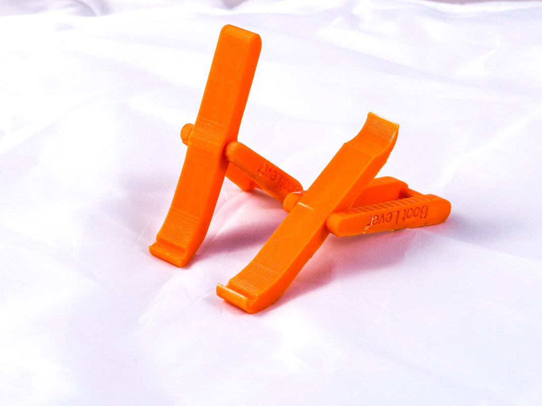
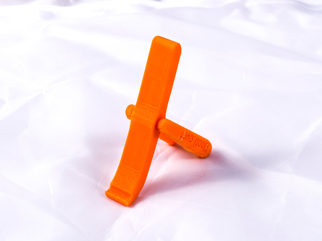
I came up with an idea for a tool to assist people who are putting on ski boots over the summer of 2018. At the time, I drew up a quick sketch of the product and got to modeling. This was early on in my CAD experience, so the design was very crude, although it did work (sort of).
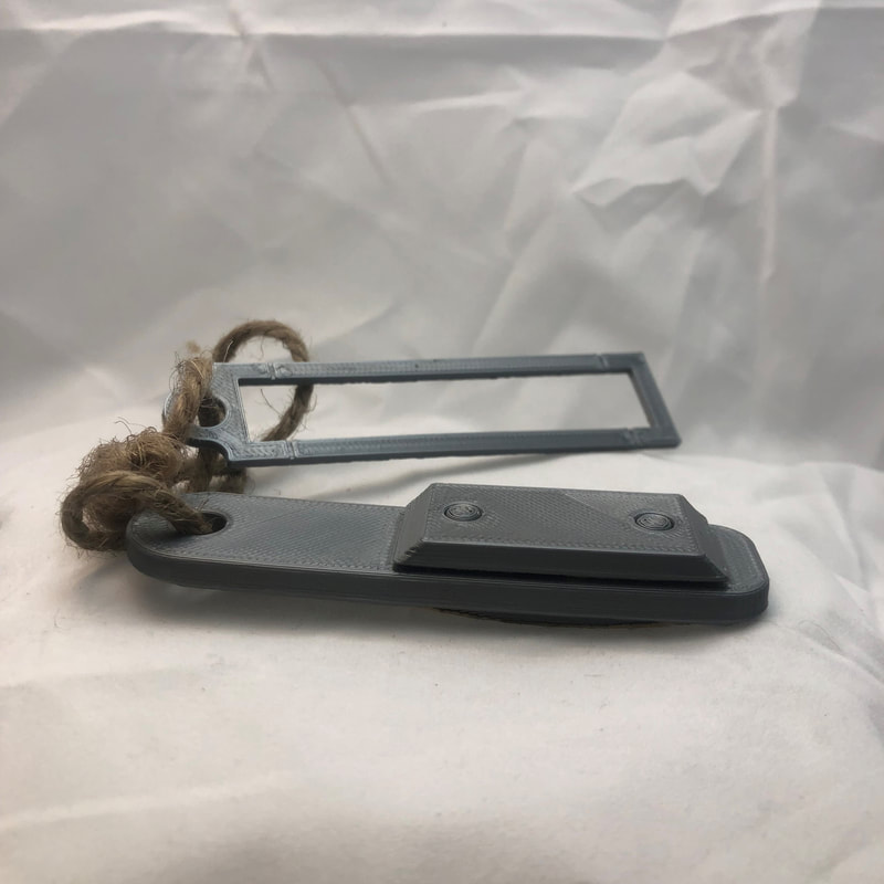
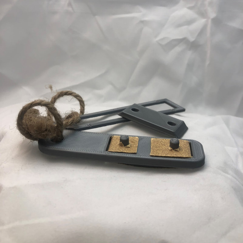
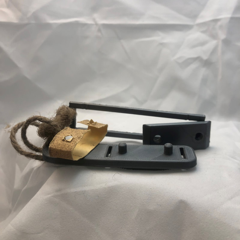
The general idea was to attach the hook side to the buckle, and the other side to the buckle hook, and through pulling the lever, you would make it easier to hook the buckle to the hook with the mechanical advantage.
The first design worked(see right) but it had some problems. First off, it was very hard to hold in your hand: the edges were very sharp, and the lever wasn't long enough to feel comfortable. Secondly, the way the hook at the end was designed, it made it hard to drop the buckle into the buckle hook because the lever hook went to far around. Also the part was showing some failure right at the pivot point (you can see it in the image).
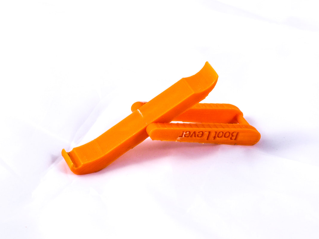
Using what I learned from the first design, I made some changes. I started by making the lever longer, smoother by adding fillets, and bulkier around the pivot. I then adjusted the hook to make it hook a lesser radius to fix the blocking problem I had before. I then added fillets to the whole design to clean it up and make it look nicer. When I tested this design it performed much better.
In the end I learned a lot about designing parts in multiple iterations, designing around failure points, designing parts that interface with other things, and human centered design. Through the process I was able to put an idea from my head onto paper, then into real life, then refined it to function better. I am happy that it was a success in this way.
The product itself has a lot of flaws that make it not such a good design. For one, while it did make it easier to buckle the boot, there is still a learning curve involved in getting it to work. When you consider this and the fact that putting on boots is only really hard for little kids, it doesn't really solve the problem. It takes a certain level of technique (and a decent amount of strength) to make it work, and for children, this would prove to be just as difficult to do. It also isn't very universal. I designed this around the dimensions of my current boots buckle and buckle hook, and when I tried it on my dads boot, it didn't fit. Certainly from a product standpoint, a lever that only works with a certain type of boot from a specific brand and style is not a very sellable product.
If I were to re design it (which I might), I would probably narrow down who I am designing it for first (whether this be children, adults, the elderly, etc.). Doing this would help me create a design that fits the problem better, and would overall result in a better design. I would also consider a way to make it universal. Doing this would make it into more of a feasible real world product that could be brought to market. Also with my current experience with CAD, I might consider designing it to be made of metal, plastic, and other materials to make it function better.
The general idea was to attach the hook side to the buckle, and the other side to the buckle hook, and through pulling the lever, you would make it easier to hook the buckle to the hook with the mechanical advantage.
The first design worked(see right) but it had some problems. First off, it was very hard to hold in your hand: the edges were very sharp, and the lever wasn't long enough to feel comfortable. Secondly, the way the hook at the end was designed, it made it hard to drop the buckle into the buckle hook because the lever hook went to far around. Also the part was showing some failure right at the pivot point (you can see it in the image).
Using what I learned from the first design, I made some changes. I started by making the lever longer, smoother by adding fillets, and bulkier around the pivot. I then adjusted the hook to make it hook a lesser radius to fix the blocking problem I had before. I then added fillets to the whole design to clean it up and make it look nicer. When I tested this design it performed much better.
In the end I learned a lot about designing parts in multiple iterations, designing around failure points, designing parts that interface with other things, and human centered design. Through the process I was able to put an idea from my head onto paper, then into real life, then refined it to function better. I am happy that it was a success in this way.
The product itself has a lot of flaws that make it not such a good design. For one, while it did make it easier to buckle the boot, there is still a learning curve involved in getting it to work. When you consider this and the fact that putting on boots is only really hard for little kids, it doesn't really solve the problem. It takes a certain level of technique (and a decent amount of strength) to make it work, and for children, this would prove to be just as difficult to do. It also isn't very universal. I designed this around the dimensions of my current boots buckle and buckle hook, and when I tried it on my dads boot, it didn't fit. Certainly from a product standpoint, a lever that only works with a certain type of boot from a specific brand and style is not a very sellable product.
If I were to re design it (which I might), I would probably narrow down who I am designing it for first (whether this be children, adults, the elderly, etc.). Doing this would help me create a design that fits the problem better, and would overall result in a better design. I would also consider a way to make it universal. Doing this would make it into more of a feasible real world product that could be brought to market. Also with my current experience with CAD, I might consider designing it to be made of metal, plastic, and other materials to make it function better.
45 Record Adapter:
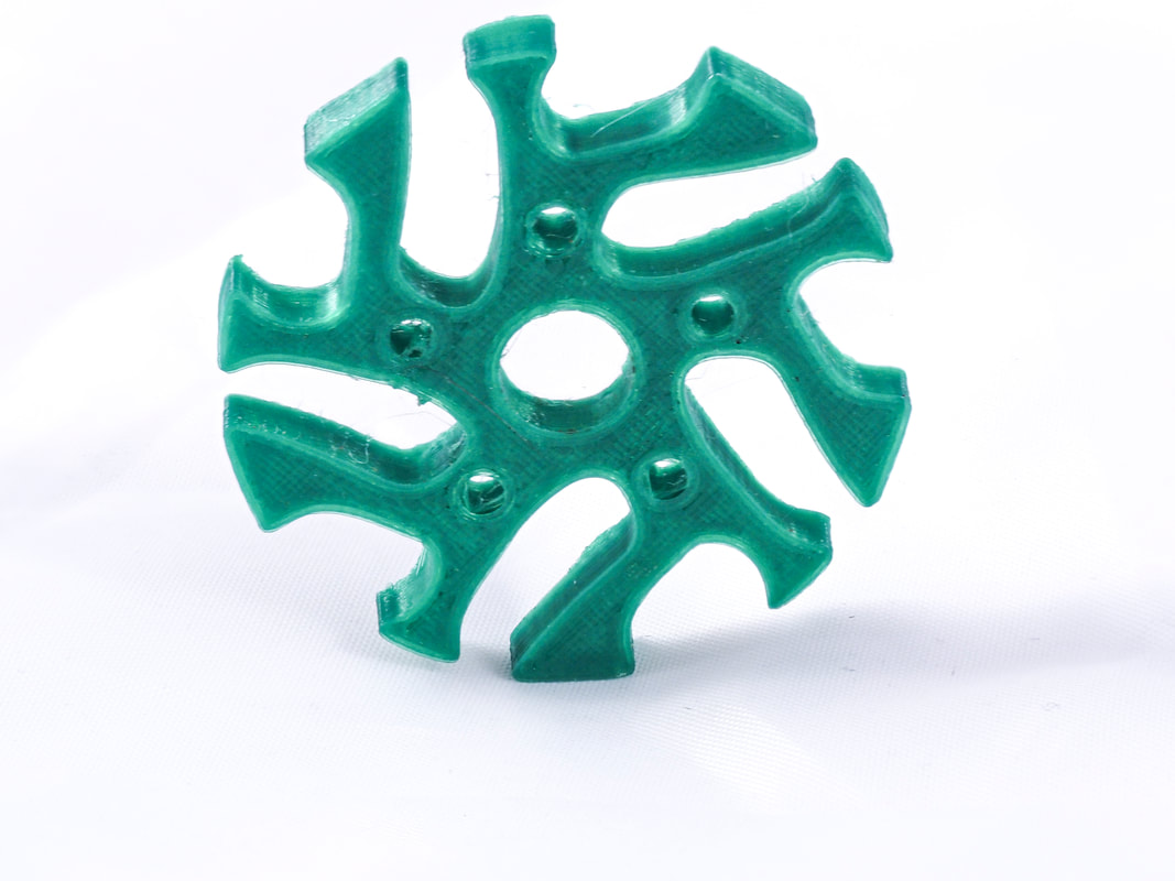
After having finished my restoration of my 40's era record player, I was inspired to design a 45 record adapter. I know records are a little before my time, but I enjoy the mechanical aspect of not only the sound stored on a physical disc, but also the mechanisms that exist in old players.
For some background on what this is, records were made in 3 formats: 33-1/3 RPM, 45 RPM, and 78 RPM. The most common format was 33-1/3, it was large enough to hold whole albums, and it featured a small hole (7.3mm) that was the standard spindle size for all record players. 45 RPM records were singles (they held a single song on each side), and had a larger hole in the middle (37mm). The reason for this size difference had to do with getting the records up to speed; 45s were usually stacked on a special spindle mechanism to play multiple songs in succession, and if the hole was as small as it was on 33s, the torque on the record when the next song dropped onto the spinning plate would cause it to go out of true fairly quickly over time. Because of this, if you wanted to play just one 45, you needed an adapter so the record fit on the spindle.
They make adapters, but at the time I didn't have one, so I figured it would be easy enough to design. I measured the inside diameter of my 45, and the diameter of the spindle and started by modeling a plain disk (with an arbitrary but reasonable thickness) with a hole through it using my measurements. from there I cut some shapes out of it and used the circular pattern tool to further alter my design and give it some visual appeal. I even made a cut using a spline on the top of the adapter to add some texture (although you cant really see it in the photos). In the end, I printed it, and it worked well.
Overall, this was a good learning experience for me. It was one of the first things I designed, and it taught me a bit about interfacing, circular patterns, and splines. If I were to do it again, I would maybe make it less thick, as the actual adapters you can buy are thinner, and the extra material isn't necessary. I would also try and experiment with different designs to practice my artistic ability with 3D modeling. If I make more, they will be shown below:
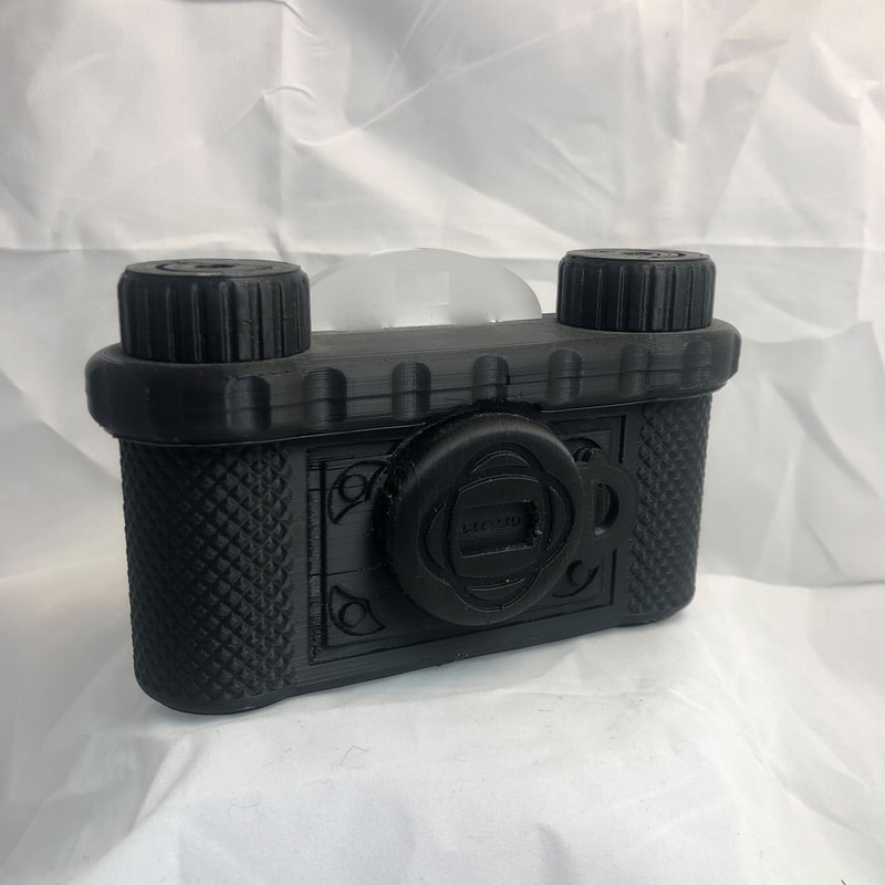
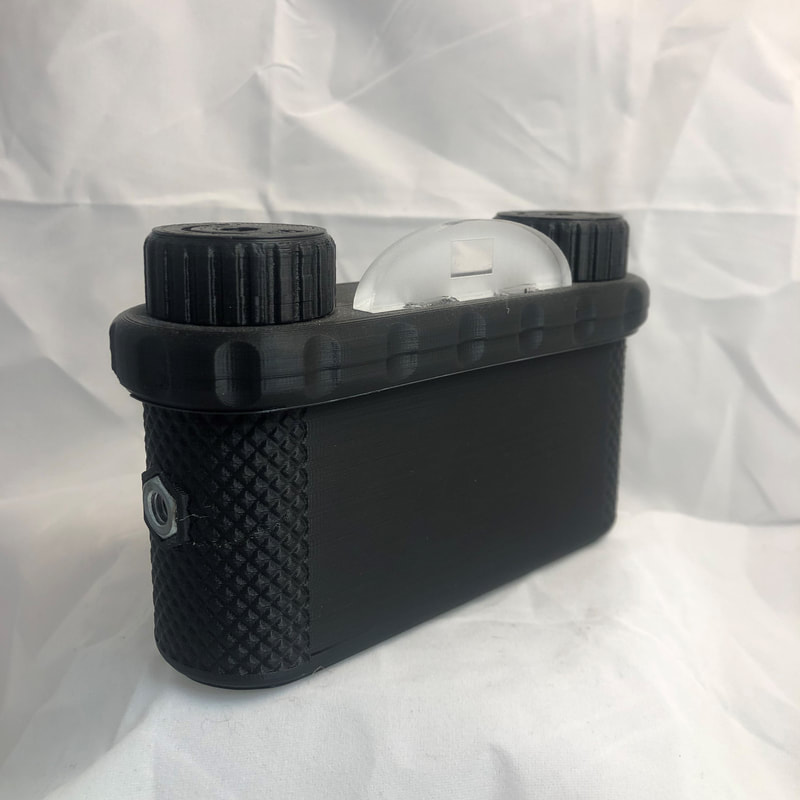
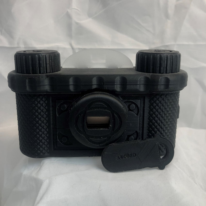
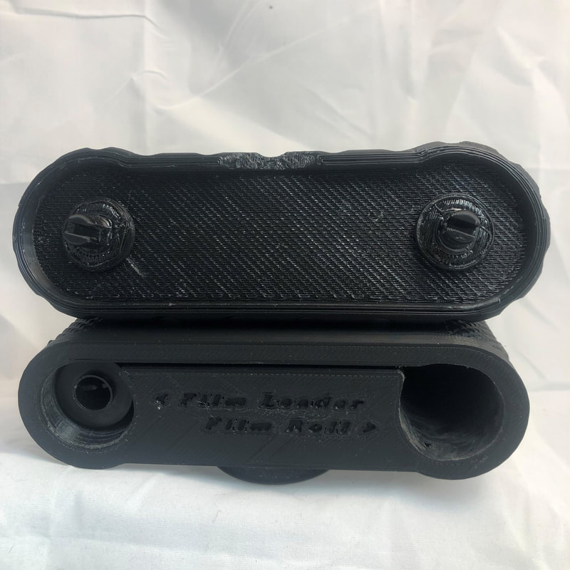
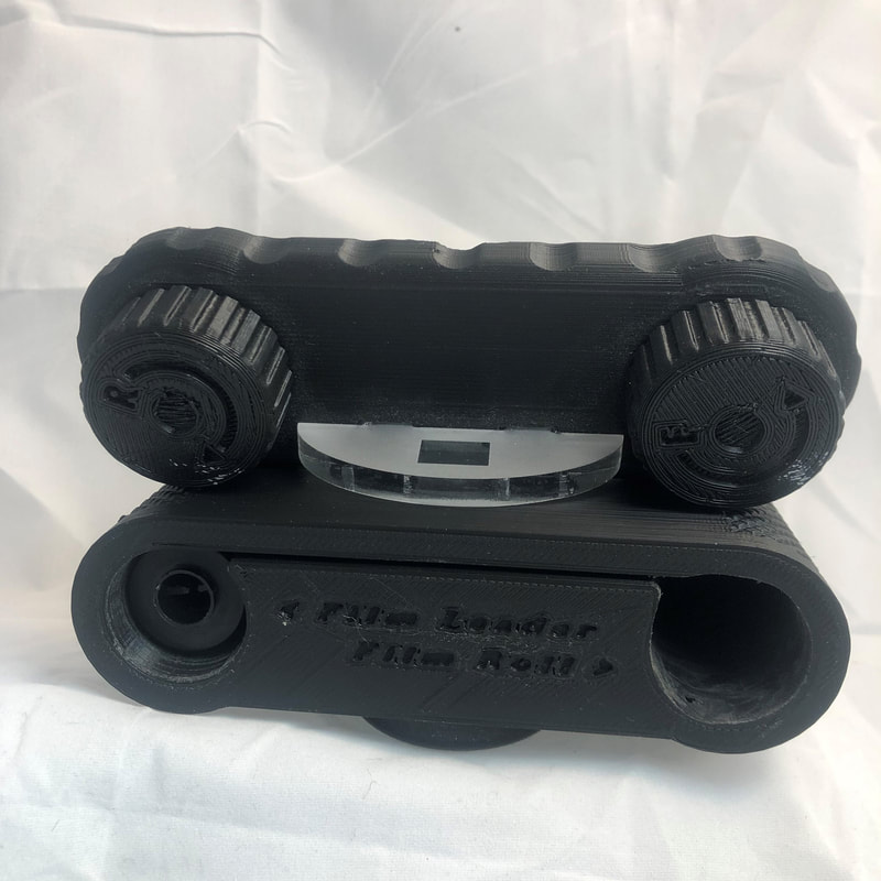
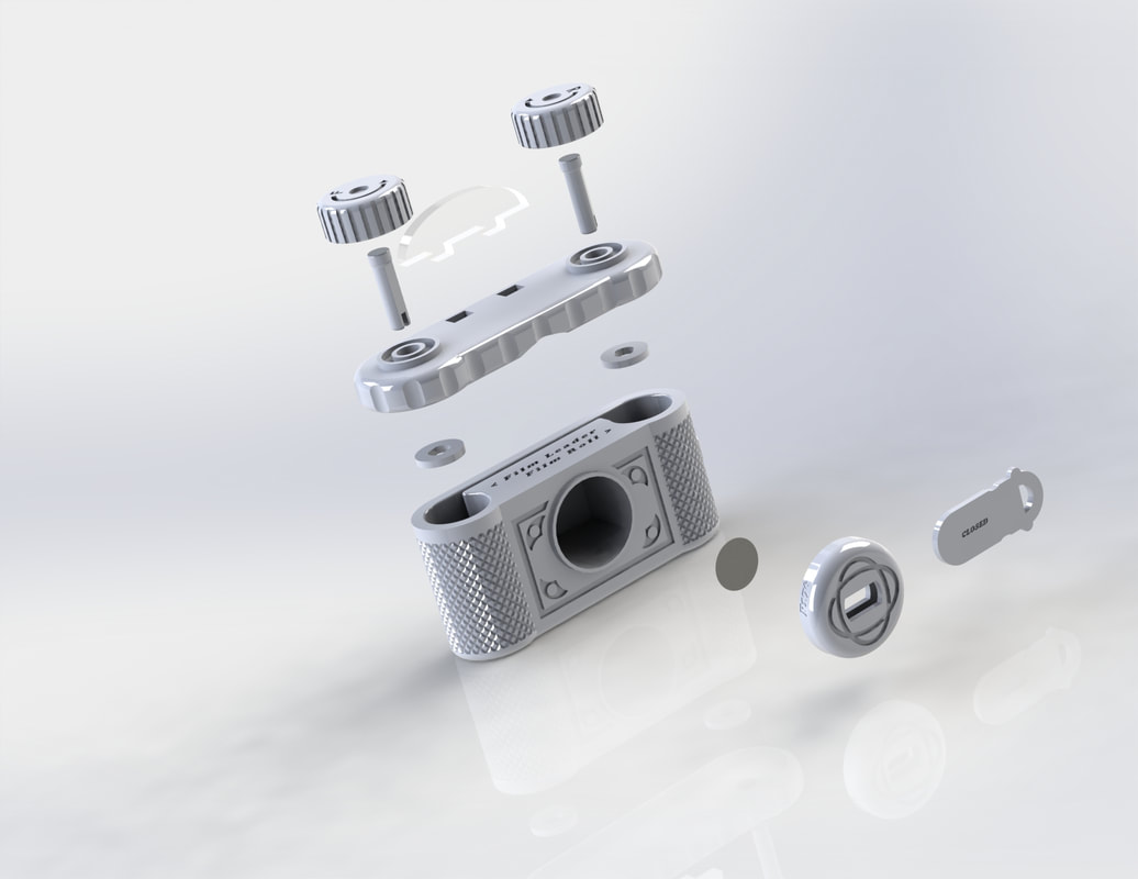
35mm Pinhole Camera
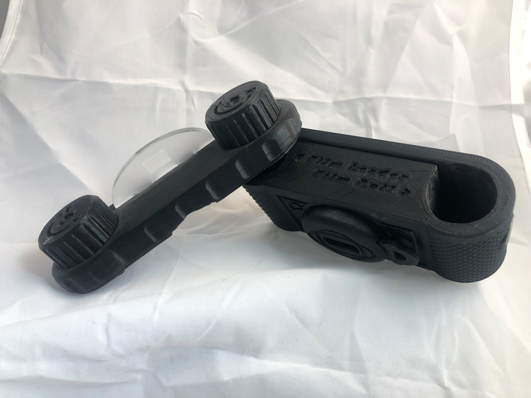
Dishwasher Indicator - Early September 2019:
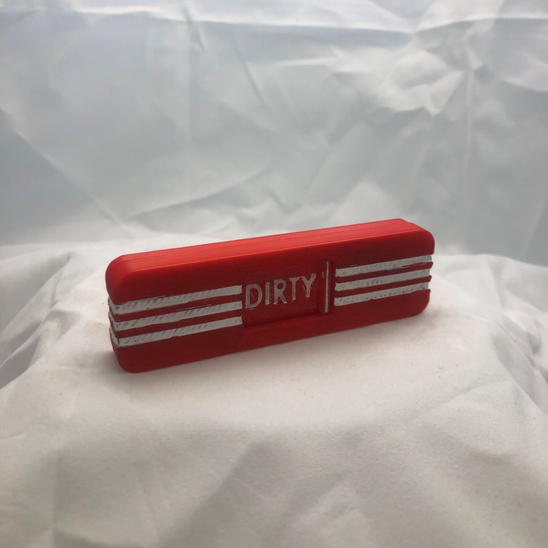
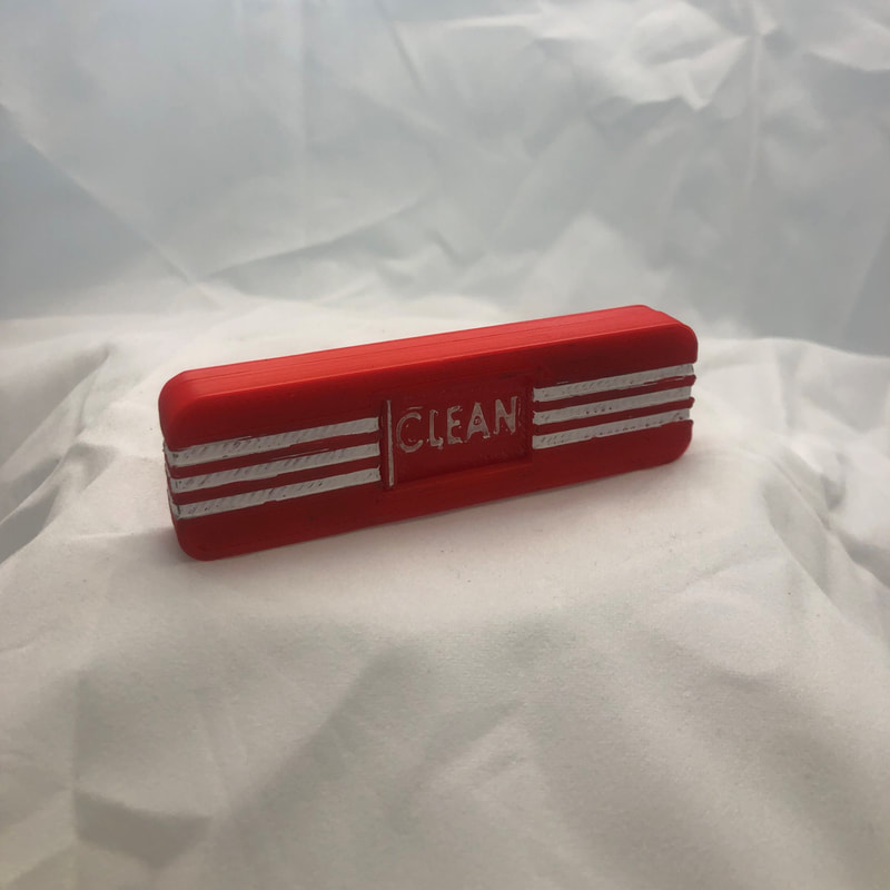
Dishwasher indicators can take the form of a commercially made product, or be as simple as a piece of paper and a magnet. The general premise is that you set the indicator to dirty when you are loading dirty dishes, when you run the wash you switch it to clean so that when the wash is done, you know you have clean dishes, and when you empty the washer, you switch it back to dirty to indicate that you are loading it with dirty dishes. This is beneficial to families or people living together, so it lets everyone know the status of the dishes win the washer (which might not be obvious). When used properly it prevents people from loading dirty dishes when there are clean ones in the washer, or from putting away dishes before they have been cleaned. I thought I would make one as a fun little project, and to further practice my modeling skills.
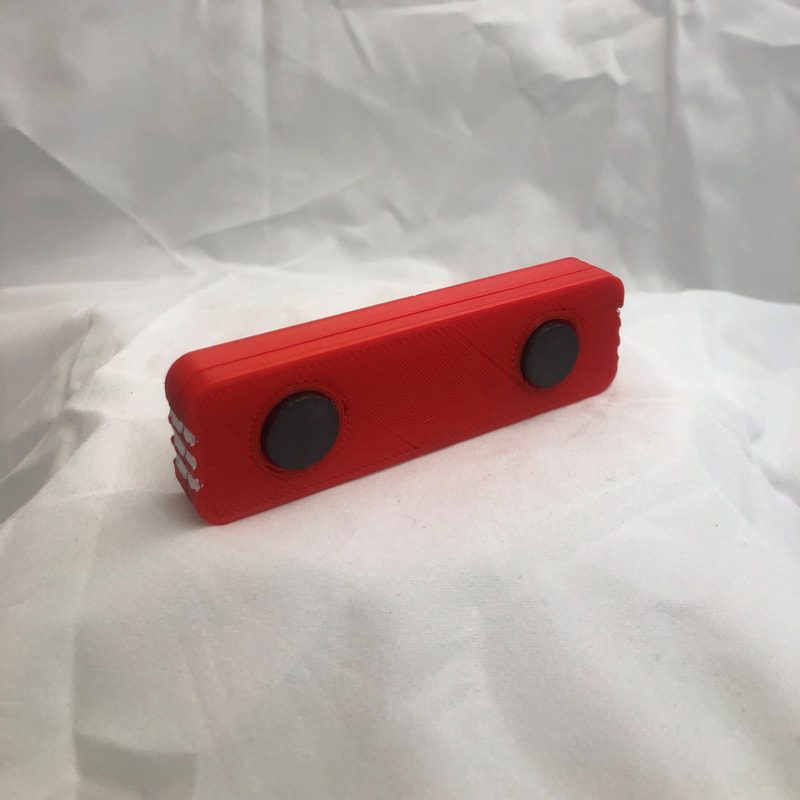
I started with a general sketch on paper. I knew I wanted the design to have a slider (slide one way and it says dirty, slide the other way and it says clean). I also wanted the slider to snap to each side so it wouldn't accidentally be changed. This aspect was important as it could easily be brushed up against as it would be at waist height, and if it were to be accidentally changed, it would completely defeat its purpose, and could actually result in miss-information. I also wanted it to stick to the dishwasher via magnets.
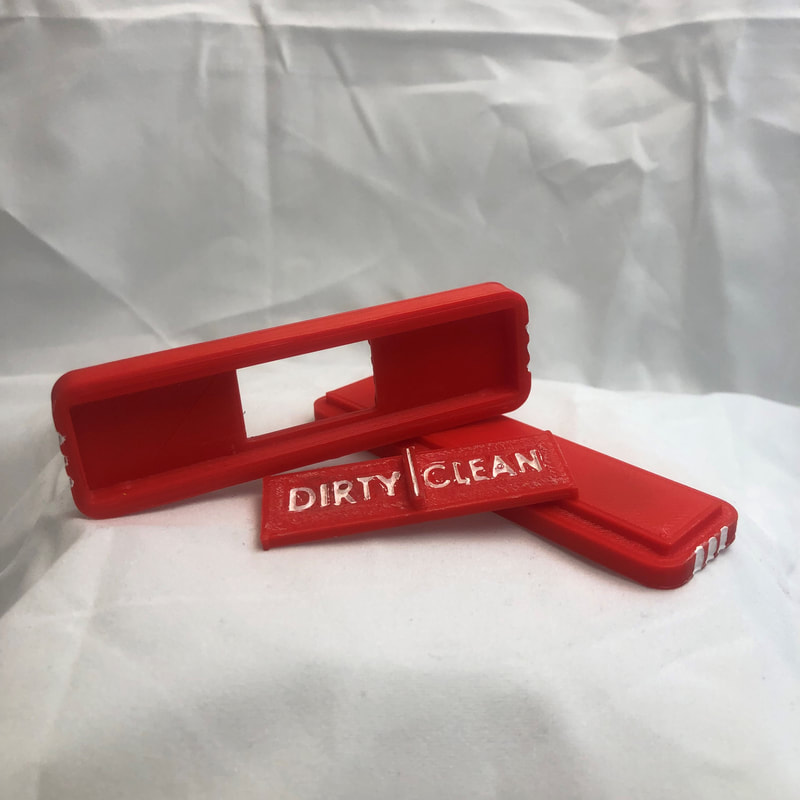
The final design ended up being three parts (a back panel, a front panel, and a slider). I went with a 50's style design as I thought that it would fit with the theme of kitchen accessories. the white part is painted on acrylic paint, and I glued in my magnets in their respective holes with epoxy. It functions the way I intended it to, and I feel that I did well to make it astatically pleasing.
If I were to do it again, there are some things I would tweak. First thing, while my snap fit design worked, It is very variable (one side snaps better that the other). I think I would completely re-design the snap mechanism, or adjust it so that it worked better the way it currently is (although it works fine for how it is). I might also fix how it the 3 pieces snap together as well. They snap together fine, but if you drop it or move the slider too quickly, it tends to fall apart. This is due to the fact that I did not have as much overlap between the front and back panels, and so the fit isn't really that tight. I could fix this by making the overlap larger, but I am content with just simply gluing the pieces together. I might also try designing a different way to display the information. I noticed while looking online and on 3D printing subreddits that 3D modeling dishwasher indicators is actually a pretty common thing that people who are into CAD do, and that there is a lot of variation in the design. In a future design of mine, I might try and display the information in a more abstract and creative way.
Overall, this project taught me a lot about interfacing parts and tolerances, as well as the aesthetic of my design. I am happy with it, and it currently sits on my dishwasher in my apartment.
I started with a general sketch on paper. I knew I wanted the design to have a slider (slide one way and it says dirty, slide the other way and it says clean). I also wanted the slider to snap to each side so it wouldn't accidentally be changed. This aspect was important as it could easily be brushed up against as it would be at waist height, and if it were to be accidentally changed, it would completely defeat its purpose, and could actually result in miss-information. I also wanted it to stick to the dishwasher via magnets.
The final design ended up being three parts (a back panel, a front panel, and a slider). I went with a 50's style design as I thought that it would fit with the theme of kitchen accessories. the white part is painted on acrylic paint, and I glued in my magnets in their respective holes with epoxy. It functions the way I intended it to, and I feel that I did well to make it astatically pleasing.
If I were to do it again, there are some things I would tweak. First thing, while my snap fit design worked, It is very variable (one side snaps better that the other). I think I would completely re-design the snap mechanism, or adjust it so that it worked better the way it currently is (although it works fine for how it is). I might also fix how it the 3 pieces snap together as well. They snap together fine, but if you drop it or move the slider too quickly, it tends to fall apart. This is due to the fact that I did not have as much overlap between the front and back panels, and so the fit isn't really that tight. I could fix this by making the overlap larger, but I am content with just simply gluing the pieces together. I might also try designing a different way to display the information. I noticed while looking online and on 3D printing subreddits that 3D modeling dishwasher indicators is actually a pretty common thing that people who are into CAD do, and that there is a lot of variation in the design. In a future design of mine, I might try and display the information in a more abstract and creative way.
Overall, this project taught me a lot about interfacing parts and tolerances, as well as the aesthetic of my design. I am happy with it, and it currently sits on my dishwasher in my apartment.
Key Topper 9/20/18:
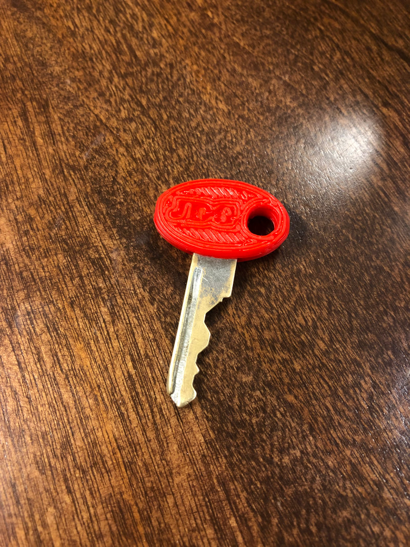
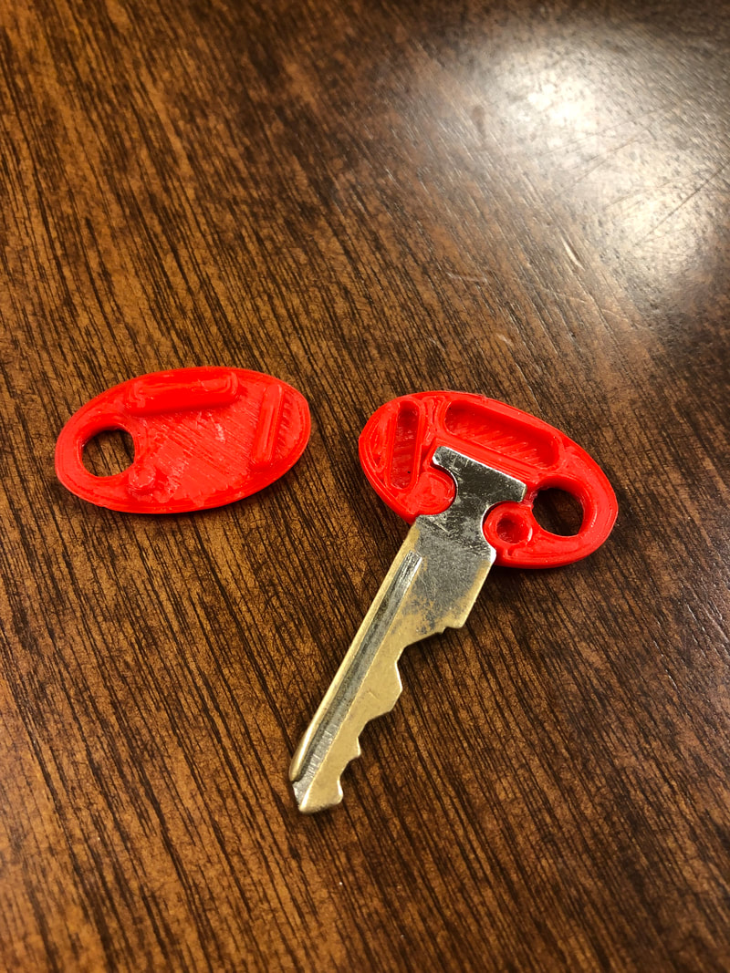
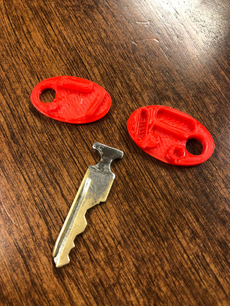
When moving out to college, my dad gave me an old cable bike lock from when he used to live in New York City. It unlocked with a simple cylinder key, and it worked very well . . . until the plastic key topper broke. At first, it was just a crack, but over time, the metal key insert started to torque out and bend more of the plastic to the point where not only was the key not functionable, but it risked falling out of the topper and off my key ring.
This was prior to me learning a decent amount of SolidWorks, and I hadn't designed many things that interfaced up to then, so my design was fairly rough and required a couple of revisions to get the metal key part and for the two pieces I printed to all fit together. I learned a lot about tolerances, and measuring parts to be modeled, and it gave me practical modeling and printing experience.
I designed it in two parts as it would have been nearly impossible (although see below) for the part to have fit into one single part. I feel that the final design works very well, its almost like a new key! I haven't had any problems with it falling apart even though it is friction fitted, and over time, I haven't noticed any degradation.
If I were to design it again, I would have probably refined the tolerances so it snapped together better (even though it fits well, its not perfect). I also would consider printing it in one piece to make it more solid by printing it to a certain layer, pausing the print, inserting the metal key part, and resuming the print (however I don't want to risk damaging my schools printers). Overall, it was a success.
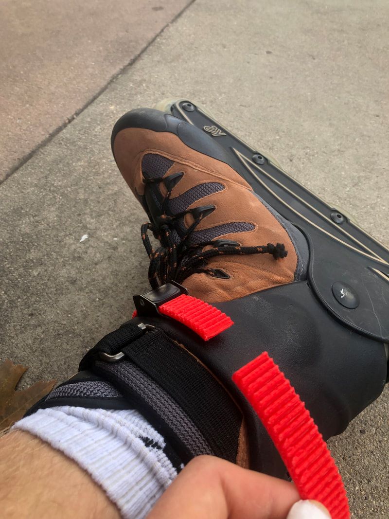
Roller Skate Strap 10/20-22/19:
I bought a nice pair of roller-skates at a local gear consignment store for only $15. The only problem was the main plastic strap was broken off, and so it didn't provide much ankle support. I did have some of the pieces, and so I decided it would be an interesting project to try and re-design the strap.
I started by measuring what I could of the ribbed part of the strap. I got a profile and cut it with a linear pattern. After that, I took measurements of the hinge to recreate it. Once I got the model done, I brought it to a 3D printer. I cut the model at the hinge and just printed the hinge first to test its fit with the rest of the buckle. It fit so I went ahead and printed the rest of it. Once it was done, it needed some work to get the support material off, and some light filing and sanding to make it fit well in the latch. Once this was done, all it needed was to be bent to shape using a heat gun, and inserted into the buckle with a nail that I modified to work as a hinge. From there, I printed one for the other side and I was off!
Overall this project was a really fun and interesting. The 3D design required me to take very precise measurements and recreate a part that was mostly gone (what you can see in the photos is all I had left of the original piece). The manufacturing process was very cool too as I did a lot of finishing to get the part to work, which is something I hadn't done much of. The whole time from the start of my design to the first finished piece took less than a day, and tested my design efficiency too.
If I were to do it again, I might have printed it in a different orientation to make it easier to take the support material off. I also would have maybe been a bit more careful with my finishing to make it look a bit nicer. In the end however, These are mainly aesthetic changes, and I am very proud of the functionality of the print.
Update 10/22/19:
In my first session out on the skates after the straps had just been completed for both (exactly 1 hour after being fully done) the left strap broke. This was due to the straps rubbing against each other, which caused the right one to pull the left one to snap.
I kind of saw this coming as the straps were unnecessarily long, and they didn't go into anything on the ends (they just hung there). When designing them I gave myself the extra length to ensure that they would fit when around my leg. Looking back on it, I should have been more precise with my measurements and not given myself so much extra length. They still function amazingly well, and the rest of the day they accumulated about 3 miles with no problems.
If I were to redesign it (which I don't currently need to, but maybe in the future I will need to replace them), I would probably just make them shorter. This would solve my problem, and would be as easy as changing one number in my SolidWorks model given how I designed it. Other ideas would be to make a strap holder on the back of the skate so it holds it close to the side, and prevents it from bending, or maybe reinforce it with metal (my friends idea). While these two ideas would probably help prevent the strap from breaking, just making it shorter seems like the easiest option.
Straight Razor:
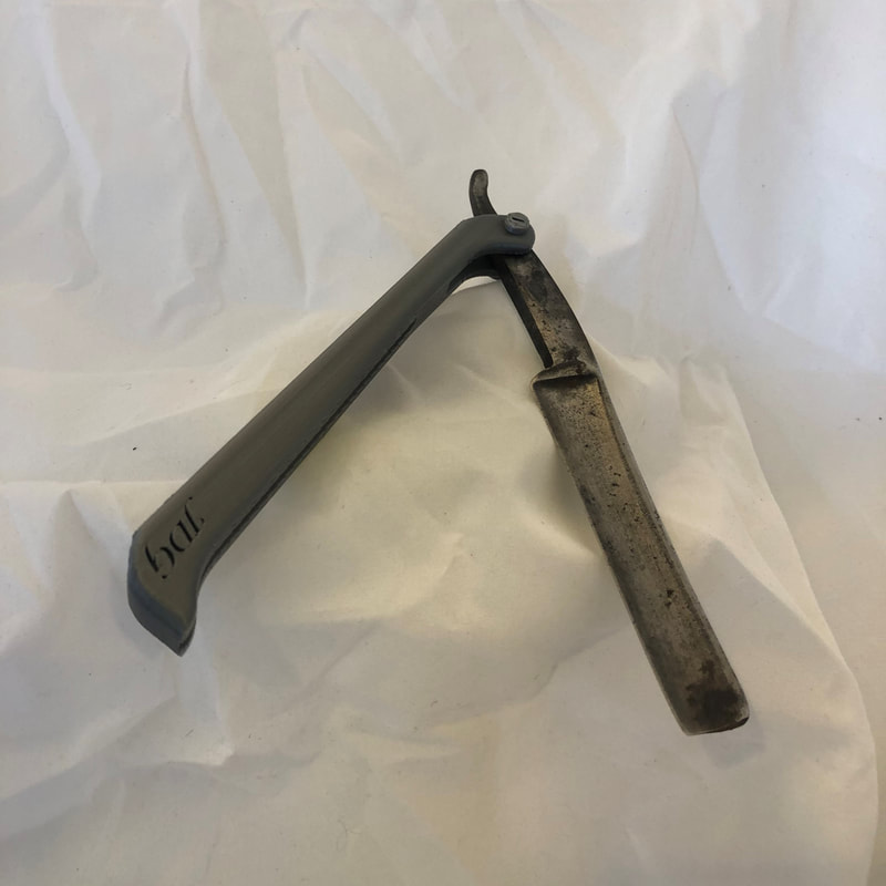
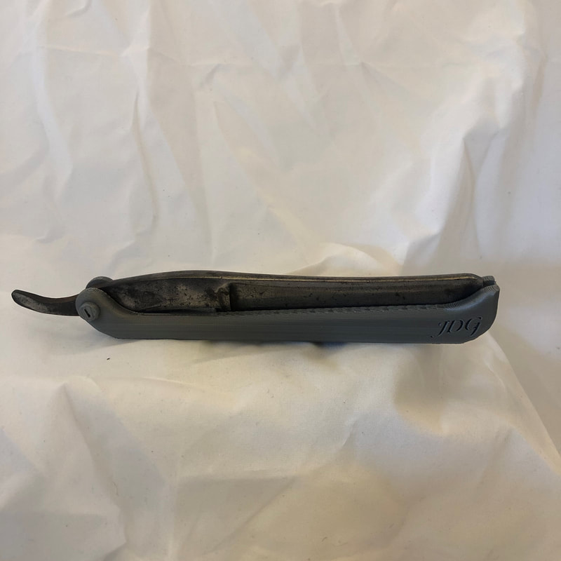
I found an antique straight razor blade from the late 1800's at a garage sale. It didn't have its scales, so I had two options: leave the blade as it is and admire it, or make some scales. I could have made them out of wood, although I had just got a 3D printer at the time, and wanted to try and design and print my own scales.
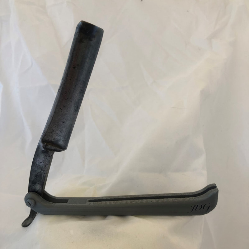
The design was fairly simple. I researched strait razor scales to get a general idea of the construction and geometry, and then proceeded to scan the blade using my home paper printer. I then uploaded the image to SolidWorks, scaled it to the right size, and began working on my design. I went with one piece as opposed to two that snap together as you might see in a traditional straight razor as it would make the design easier. I assembled it with a 3D printed pin, and incorporated my initials into the design to give it a personal touch.
Overall the design worked well. It printed easy and everything fit together cleanly. I learned a little bit about fitting parts together, using images to aid in design, and taking range of motion into account. While I have yet to use the finished product, I have held it and pretended to use it, and I can't see how the part would interfere anymore than the scales it originally had would have.
I would change a lot if I were to re-design it. For one, Although it functions well, It doesn't fit the bevel of the knife, the knife just rests on a flat surface. Doing this would make it more accurate to a real straight razor, and would hold it together better when closed. Also, while the design itself looks sleek and classy (IMO), It isn't very much like the traditional scale style. Finally, while the grey plastic was the least tacky of the color options I had (the others being green and orange), I felt that brown or cream would make for a more appealing color. The ultimate material would be wood filament, and maybe in the future I will use it for a re-design.
Hand File - Summer 2019:
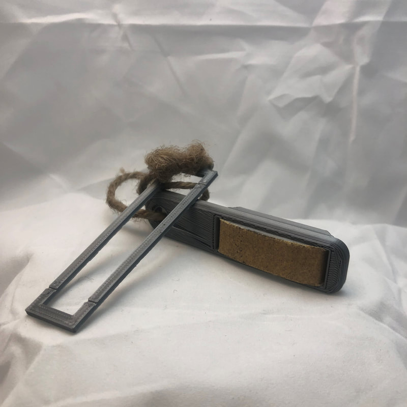
Over the summer of 2019 I worked at a climbing gym. This got me more into the sport, and resulted in my hands becoming very callused and beat up. They make little files that are for sanding down your calluses so they don't get too big (the bigger they are, the more likely they will rip off, which is painful and can put you out of climbing for a week). The problem that I saw with these files is that they're fairly expensive for the amount I would be using them, and the sand paper is usually not interchangeable (and if they were, there weren't that many options, and they were also expensive). I wanted a way for you to replace the paper fairly easily, without having to buy expensive pre-made sandpaper pieces. I had a 3D printer, and a solid product idea, so I got to work.
I started by sketching out the idea on paper. I wanted you to insert a sandpaper strip across the file, and secure it so that you could easily put it on and take it off (this way, you could replace the paper easily, have multiple grits of paper strips that would be easily interchangeable, and you wouldn't have to deal with stick-on strips). I also wanted it to be small so it could easily fit in your bag. From this design, I also made a cutting stencil that made cutting new strips easy and very cost effective (you could make your own strips from hardware store sand paper sheets).
I was very happy with the final design. It felt good in the hand, worked very well, and assembled nicely. I even had a few people ask me what it was in the gym, and they thought it was a cool idea. I learned a lot about interfacing parts, and human centered design.
If I were to do it again, I might tweak the mechanism for the sand paper. While it allows the user a lot of freedom when it comes to their choice of sandpaper, it does require a fairly steady hand and some skill to cut the paper strips out. I might remake the design so that you don't have to cut slits to fit the paper onto the nubs, and make it so you can just cut the strip out and clip it between the file and the cap. I also might make the rounded part of the file larger. This would allow you to file better.
More below:
Android Robot Mount - Spring 2018:
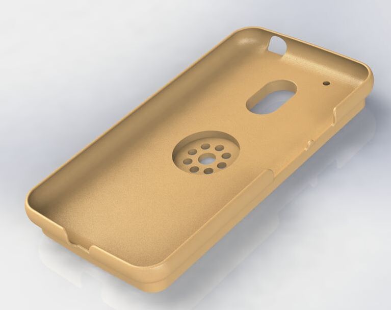
In high school I was a part of my robotics club. We designed and built a robot that was meant to perform tasks as outlined in the First Tech Challenge robotics competition, by utilizing stepper motors, DC motors, aluminum framework, pulleys, motor controllers, Android phones, etc. One aspect of the robot that was challenging for us to fix was the mounting of the Android phones. The phones allowed us to control the robot via a Bluetooth remote, but we hadn't figured out a secure way to mount the phone to the robot itself. At the time, the phone was literally just balancing freely on the robot chassis.
I was put in charge of formulating a solution to this problem. I first searched online for an android case file that would fit our phone. Once I found that, I loaded it into SolidWorks and Started by extruding a bottom surface below the case to ensure we had a flat surface, and that we had enough depth for the screws to secure it safely. After this, I measured one of our aluminum frames screw patterns and modeled it onto the case and did an extrude cut. I then cut a recessed circle over the pattern I cut to ensure that the screws would have enough clearance and wouldn't interfere with the phone. After this I was done, and I printed it, brought it to our group where we tested it and it worked perfectly.
All in all, it was a huge success. From It I learned more about interfacing parts, a recreating things with patterns, and taking interferences into account. It worked perfectly the first time after printing it, and as far as I am aware, the club still uses it.
If I were to do it again, there isn't too much I think I would change. It worked perfectly for our application, and didn't take up that much space. Maybe If the group needed it to be more compact, I would redesign it to hold the phone similar to a phone holder you might see in a car. This would allow it to hold the phone outside of the center of the robot, and might provide more room if needed.
Earrings - Early December 2019:
I was Inspired to try and design earrings as the holidays were coming up, and I thought my mother and sister would love some as a gift. I had a good amount of experience with the laser cutter, but I hadn't really done anything too complex, or with engraving, so I was up to the challenge.
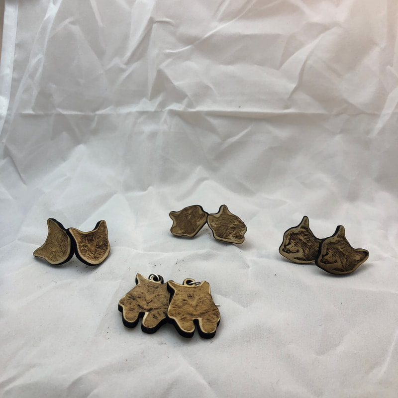
I first tried to come up with an idea: I did some brainstorming, I consulted my father on what they might want, and in the end, I decided that making my cat into an earring would be challenging but also the perfect gift. After sampling a few images of my cat, I took them into photoshop, cropped and edited them to make them have more contrast (made them b&w and adjusted the levels). I knew the contrast was important, but due to my lack of experience with engraving on wood, I was unsure of how necessary it was.
After this I went to the craft store and found some earring posts, hooks, and jump rings. From there, I imported my edited cat images into SolidWorks and started by scaling my image to an appropriate size. I drew an outline using the spline tool, and exported the outline as a DXF to be used on the laser cutter.
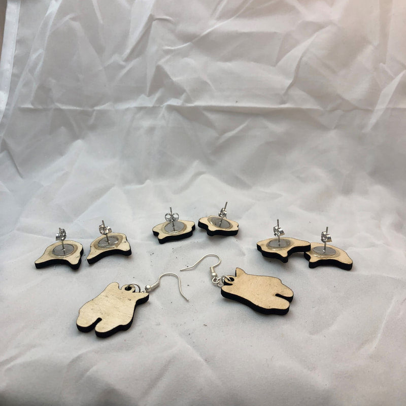
When cutting, I used 1/16" birch plywood. The engraving seemed to work fairly well using the settings provided in the laser cutting room for wood, but I ended up lowering the speed by 20% to get a darker image. Once I got my cut-outs, I glued the backs on with epoxy and used pliers to attach the hooks to the hanging ones. In the end, I had a very nice set of earrings as gifts for my mother and sister.
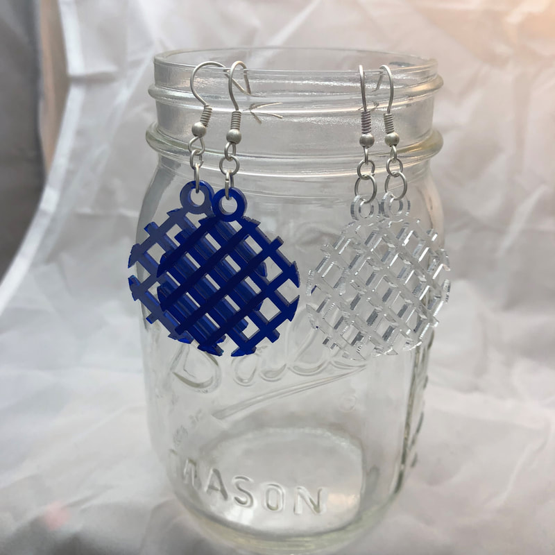
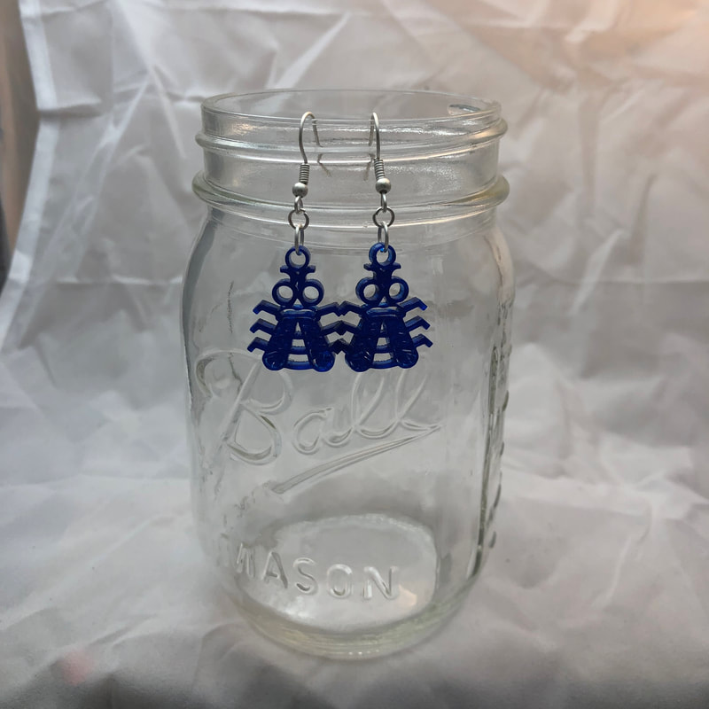
I also experimented with some more abstract designs (see above). I made a grid design as an initial test for acrylic, and then I went with a more complex "bee" design, which also seemed to work well too. Both were designed in SolidWorks.
I really enjoyed making these earrings, and I learned a lot which I can use in future projects. For one, I learned that the contrast does in fact matter. One of my cat designs did not look all that clear, and I think it was because it did not have enough contrast. Going forward, I will definitely take contrast into consideration when engraving with the laser. Also, The "bee" design did not come out exactly as I had hoped it would. Some of the laser cut hole designs on it were too small and ended up fusing instead of cutting out. In the future, I will definitely consider the size of what I am cutting in order to ensure that the laser can actually cut it out.
Overall, the process was fun and enjoyable to me. I learned more about using the laser cutter and I now feel more confident with it. I might try and make more earring designs in the future, and maybe try and sell some of my designs online or at local craft fairs.
I first tried to come up with an idea: I did some brainstorming, I consulted my father on what they might want, and in the end, I decided that making my cat into an earring would be challenging but also the perfect gift. After sampling a few images of my cat, I took them into photoshop, cropped and edited them to make them have more contrast (made them b&w and adjusted the levels). I knew the contrast was important, but due to my lack of experience with engraving on wood, I was unsure of how necessary it was.
After this I went to the craft store and found some earring posts, hooks, and jump rings. From there, I imported my edited cat images into SolidWorks and started by scaling my image to an appropriate size. I drew an outline using the spline tool, and exported the outline as a DXF to be used on the laser cutter.
When cutting, I used 1/16" birch plywood. The engraving seemed to work fairly well using the settings provided in the laser cutting room for wood, but I ended up lowering the speed by 20% to get a darker image. Once I got my cut-outs, I glued the backs on with epoxy and used pliers to attach the hooks to the hanging ones. In the end, I had a very nice set of earrings as gifts for my mother and sister.
I also experimented with some more abstract designs (see above). I made a grid design as an initial test for acrylic, and then I went with a more complex "bee" design, which also seemed to work well too. Both were designed in SolidWorks.
I really enjoyed making these earrings, and I learned a lot which I can use in future projects. For one, I learned that the contrast does in fact matter. One of my cat designs did not look all that clear, and I think it was because it did not have enough contrast. Going forward, I will definitely take contrast into consideration when engraving with the laser. Also, The "bee" design did not come out exactly as I had hoped it would. Some of the laser cut hole designs on it were too small and ended up fusing instead of cutting out. In the future, I will definitely consider the size of what I am cutting in order to ensure that the laser can actually cut it out.
Overall, the process was fun and enjoyable to me. I learned more about using the laser cutter and I now feel more confident with it. I might try and make more earring designs in the future, and maybe try and sell some of my designs online or at local craft fairs.
12/15/19:
Once finishing my cat earrings, I was notified that I had one of my friends for a multi-family Secret Santa. I could have just gotten a gift online, but having just designed earrings, I figured I might as well try to make some more. Also, I felt that she would love these over anything I could have bought: she is into art and design.
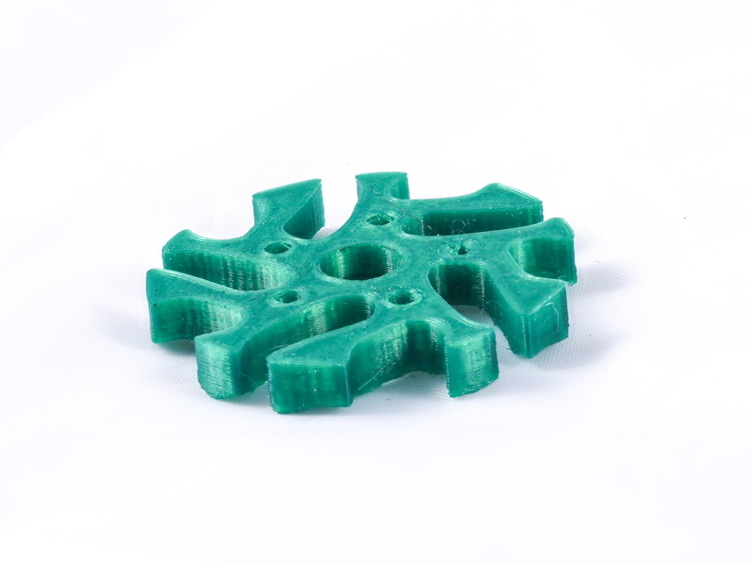
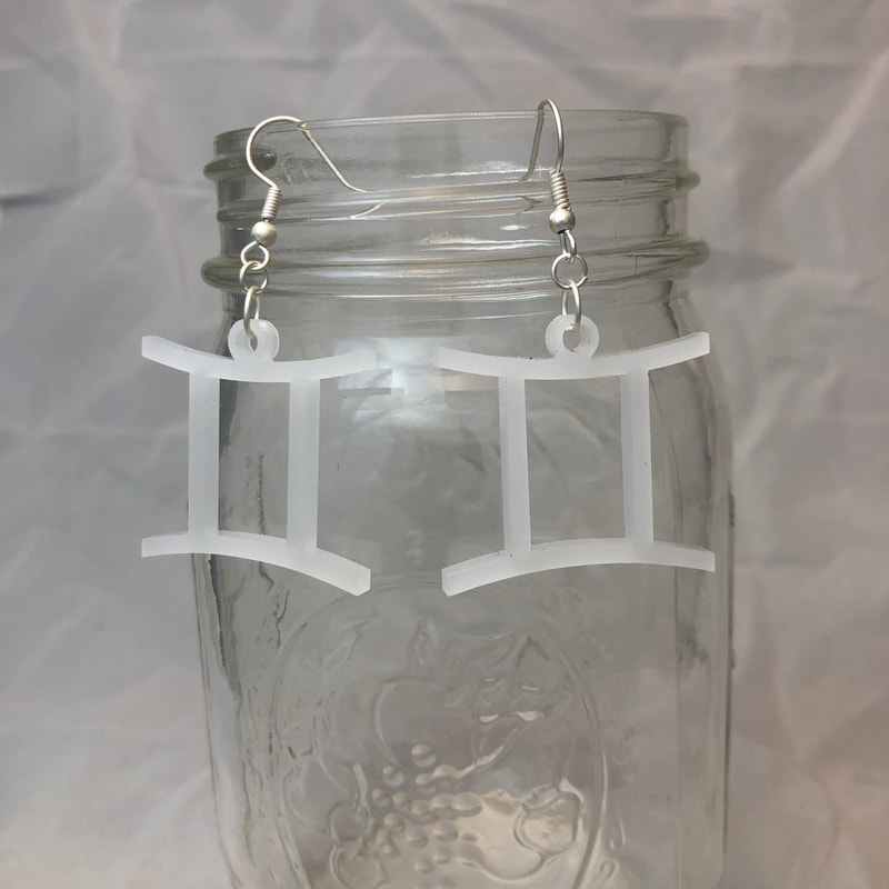
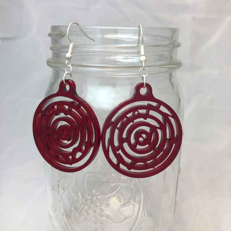
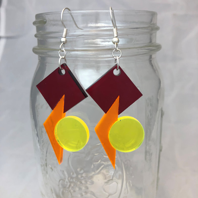
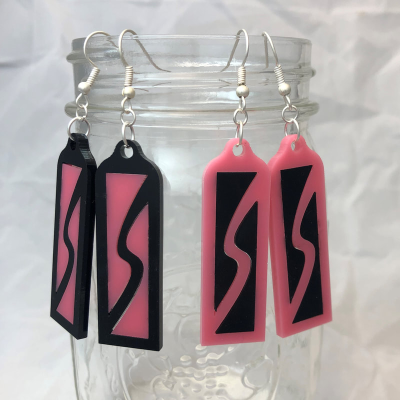
After consulting a friend of my friend who I knew from my AP Studio Art class, I had a rough idea of what my designs should center around: Retro and colorful. I initially started with the red circular one; It features concentric circles connected with wavy splines. This one was complex in design but was only comprised of one piece. From there I made the rectangular "S" design (her name is Sam). This design was more simple, but I intended on inlaying other pieces of acrylic in the earring, so It would prove to be a bit of a challenge. The third design was the shape one; this one solely featured pieces that fit together, and I worked hard on this one to make sure the center of mass fell so that the earrings hung the way I wanted them to. Finally, the Gemini earrings were my last design: they're simple but clean and appealing.
I am very proud of my work with this set. Not only did I practice my modeling skills (and SolidWorks analysis with the center of mass), but I also was able to practice my creative design when it comes to the color and the actual style of the earrings. I feel that I produced designs that reflect my initial focus, and although at the current moment, I haven't yet given them to my friend, I feel that she will love them.
I have considered designing more earrings and forming an online store for them as I think they would be something people would buy. I haven't worked out all of the logistics nor do I have nearly enough designs, but I plan on testing it out to see if I can turn this into a successful and potentially profitable endeavor.
Laser Cut Bowl - December 2019:
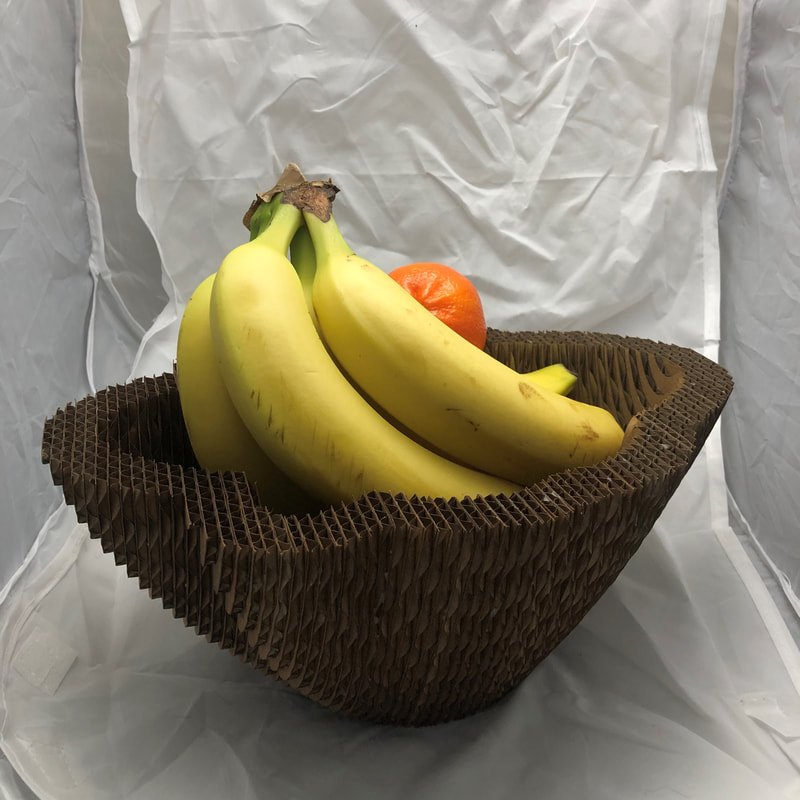
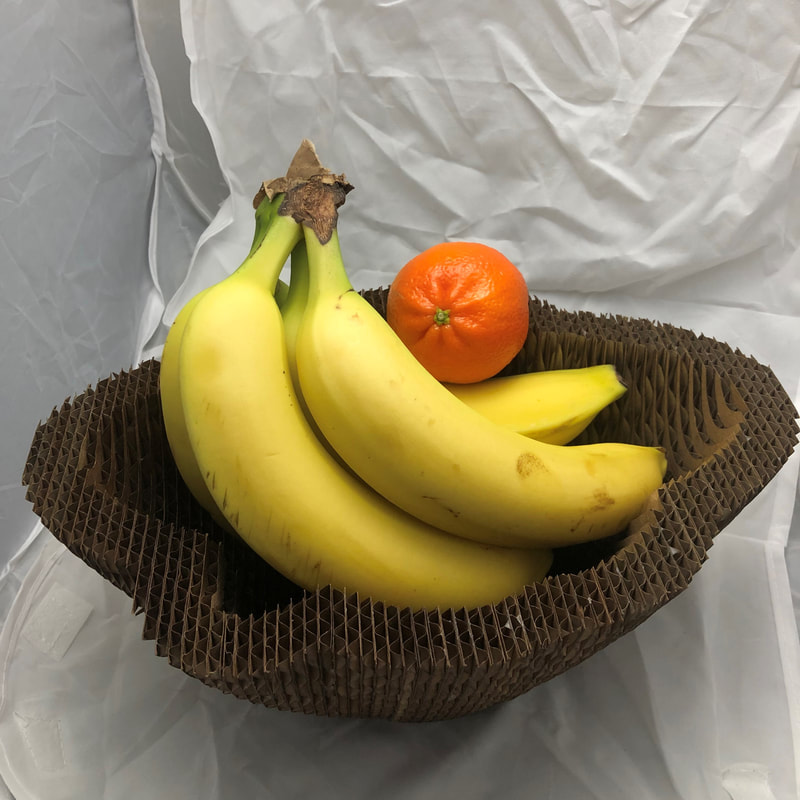
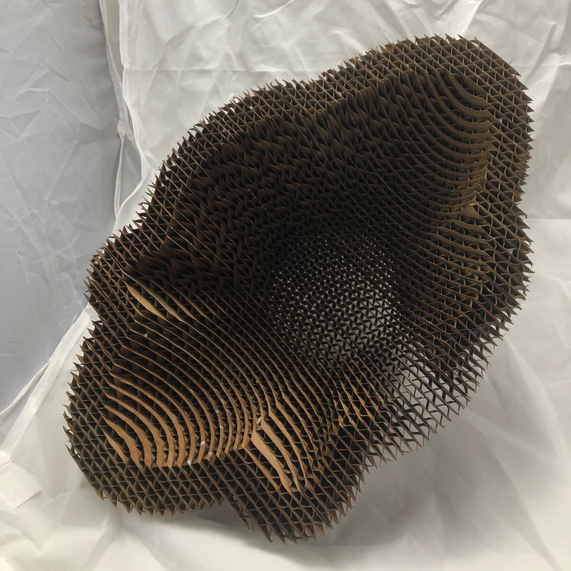
I was inspired to make a laser cut sliced object out of cardboard ever since I saw the sliced cardboard buffalo on the wall in the laser cutting room in the ITLL. I liked how it was made up of individual 2D layers to form a 3D object with interesting texture. I wondered if I could make something 3D from 2D layers, but I also wanted it to be functional, so I decided to design a fruit bowl.
I started with a few hand sketches and made general measurements to approximate size. After that I played around with shapes in SolidWorks to create the bowl that I wanted. I didn't want to make it too complex, but I did want it to have some character. Once I was pleased with the design, I needed to slice it. I found that size C cardboard was fairly abundant and a reasonable thickness. I sliced the model and saved each slice as a DXF file. I then cut all of the pieces on the laser cutter and glued them all together.
When it was finished, it looked very good and was a lot sturdier than I expected. I was also very pleased with its utility as it actually functioned really well as a fruit bowl. Overall it was a success.
If I were to do it again (which I do plan on doing), I would do a couple of things. First I would increase the complexity of the bowl. I think this would challenge me more, and would also create more interest with the piece; I think there are a lot of interesting things you could do that utilize the topographic like nature of the cardboard slices. I would also make it easier to align the pieces. It wasn't too hard with this bowl, but something with a more complex design could benefit from notches, a paper template, or even a design consideration that utilizes a datum edge or corner.
