Impactful Classes:
GEEN 1400: First Year Engineering Projects

I took GEEN 1400 my spring semester of my freshman year (Spring 2019). In this class, we were put into groups of 5 engineers from different majors, given a client with an engineering problem, and worked to design a solution while utilizing the tools and the knowledge of the ITLL and its staff. Along the way, our professor, Dr. Malinda Zarske, provide us with useful lectures on topics ranging from engineering ethics to skills for design considerations.
The Innominates:
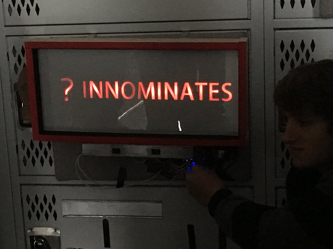
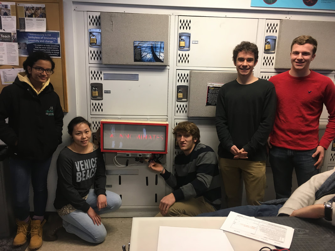
When deciding on a group name, someone suggested "The Innominates" as kind of a joke to say that we didn't have a team name, but we ended up liking the name as it had a nice ring to it. Our first project as a group was to design a "billboard" to hang on our locker. It had many constraints: The size of the door panel, it needed to utilize an Arduino, it needed to have at least two ways to interact with it, and it needed to have parts made through 3D printing, laser-cutting, and machining.
The way out team tackled this was to brainstorm ideas right off the bat. We ended up coming up with a lot of ideas this way and would do a lot of this during our main project. We then determined what we needed to make, and split up the work. Due to the fact that some people did not have as much hands on fabrication experience, we paired group members with less experience with group members with more experience on certain tasks so as to allow for everyone in our group to become familiar with the different fabrication tools we had access to.
In the end, our initial project came together very well. It featured paper over laser cut wood backlit with LED's behind an acrylic sheet to give the impression of a screen. When turned off, you couldn't see the letters that would be on the screen, and so it looked very clean. You could interact with it by turning on and off the lights that lit our name and the symbol independently, and you could spin the wheel on the side to change the symbol as well. it hung on our locker with machined aluminum hooks and was powered by an Arduino Uno. We won best design among the 5 groups in our class at the discretion of our professor.
The Catio:
A Catio is an outdoor cat enclosure, cat + patio. Our client was a family in the Greater Boulder area, who needed a way for their cats to go outside but also be protected from possible threats to the cats safety. During our first interview with them, we discussed what they wanted and some constraints:
At the end, we displayed our creation at the design expo, and got a lot of feedback from the people who attended. Our client even came and brought one of their cats to test it out. After expo, we installed the catio on their porch where it currently sits today.
I learned a lot from taking this class, and gained a lot of experience. Working in groups was not new to me, but working in groups to design and build something was. I utilized my group working and leading skills, and learned some along the way to help further our groups success. I also got to work for a client for the first time. from this I learned more about how to design for someone else: what types of questions to ask, what to promise, and how to correspond professionally over the course of the design process. I also gained valuable hands on experience. We used drills, wood shop tools like table saws, bandsaws, drill presses, and sanding belts, as well as paints. We also worked with many different materials such as wood, metal, roofing plastic, chicken wire, and plastic liner. Overall the design process was a fun and informative experience, I learned a ton about working on a team in an engineering setting.
- It needed to be sturdy to withstand weather, wild animals, and their two large dogs
- It needed to have access to the inside of the house
- It needed to have a way for people to get inside to grab the cats if need be (although it should not be designed to have people in it normally)
- It needed to provide shade
- It needed to look natural and fit with the house color scheme
- It needed to be fully disassembleable (preferably by two people and with no tools)
- It needed to fit within the constraints of the porch and the porch swing
At the end, we displayed our creation at the design expo, and got a lot of feedback from the people who attended. Our client even came and brought one of their cats to test it out. After expo, we installed the catio on their porch where it currently sits today.
I learned a lot from taking this class, and gained a lot of experience. Working in groups was not new to me, but working in groups to design and build something was. I utilized my group working and leading skills, and learned some along the way to help further our groups success. I also got to work for a client for the first time. from this I learned more about how to design for someone else: what types of questions to ask, what to promise, and how to correspond professionally over the course of the design process. I also gained valuable hands on experience. We used drills, wood shop tools like table saws, bandsaws, drill presses, and sanding belts, as well as paints. We also worked with many different materials such as wood, metal, roofing plastic, chicken wire, and plastic liner. Overall the design process was a fun and informative experience, I learned a ton about working on a team in an engineering setting.
ATLS 1100: Design Foundations
MCEN 1025: Computer-Aided Design and Fabrication
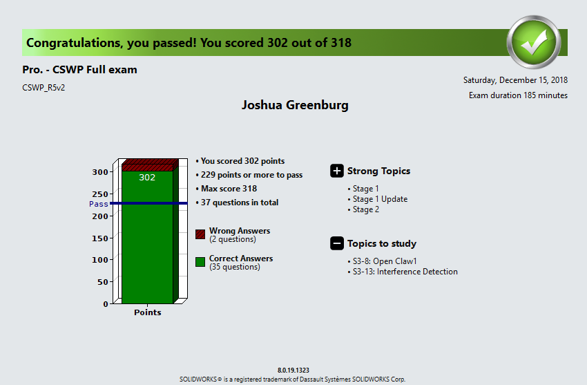
I took MCEN 1025 my fall semester of my freshman year (Fall 2018). Through the course, we worked in SolidWorks, learning the tools and tricks in order to improve our 3D modeling skills and attempt to get certified at the end of the semester. Aside from our class assignments and homework, we also manufactured a toy car in groups, and did a final project that consisted of modeling a multi-piece object.
General Coursework:

The course was structured in a lecture-recitation format. In lecture we would be introduced to the new SolidWorks topics and tools we would be using in recitation that week, and would occasionally be shown different processes that companies use to manufacture parts and products. This spanned from lathes, mills, and CNCs (subtractive manufacturing) to 3D Printing and laser sintering (additive manufacturing) to working with Sheetmetal and injection molded parts. In recitation, we would practice our modeling skills through a guided lab activity and a homework assignment that we would do on our own. We went over a lot of SolidWorks Topics:
- Sketches
- Navigating views
- Cuts, extrusions, lofts, sweeps, patterns, etc. (modeling tools)
- Reference geometry
- Smart and efficient modeling habits
- Configurations (parts and assemblies)
- Custom and material properties
- Assemblies
- Mates (including advanced mates)
- Drawings (parts and assemblies)
- Sheetmetal (modeling and drawings)
- Modeling for injection molding
- GD&T
- Parametric modeling
- Utilizing McMaster Carr
- 3D rendering
Toy car:
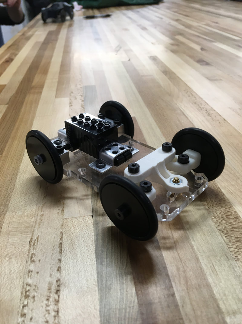
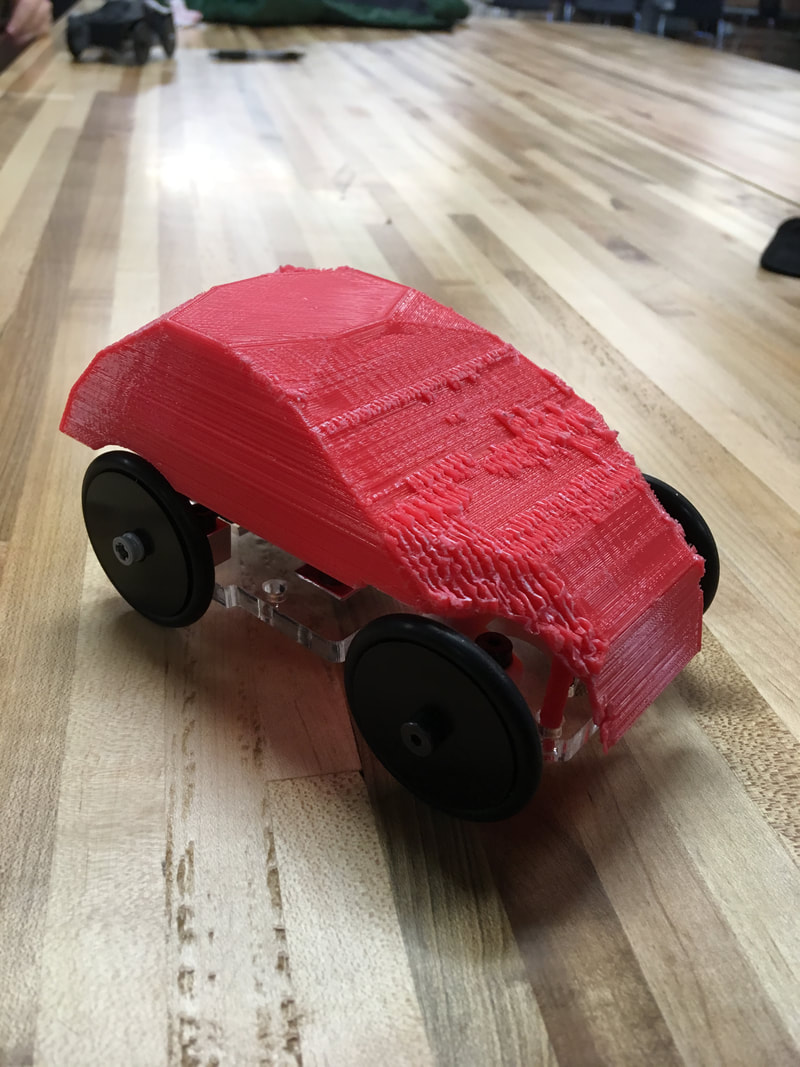
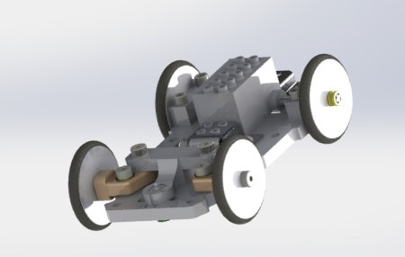
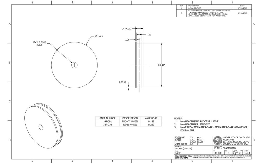
As a part of the lab assignments, we ended up modeling and creating drawings of the parts of a model pullback car that we would fabricate in a group, Some of the parts we got pre fabricated from our professor, and others we had to make ourselves. Of the parts we made ourselves: The wheels were made from Delrin on a lathe, the chassis was laser cut acrylic, the motor mounting brackets were machined on a mill and bent into shape using a mold, the car body was 3D modeled by us and 3D printed, and the rear axel bearings were also machined on a mill. Assembling the car, we tapped holes and glued parts together. The car performed well and we were proud of what we produced. I was particularly happy with the project as I gained valuable experience not only with CAD but also with fabricating parts on different machines.
Final Project (Carabiner assembly):
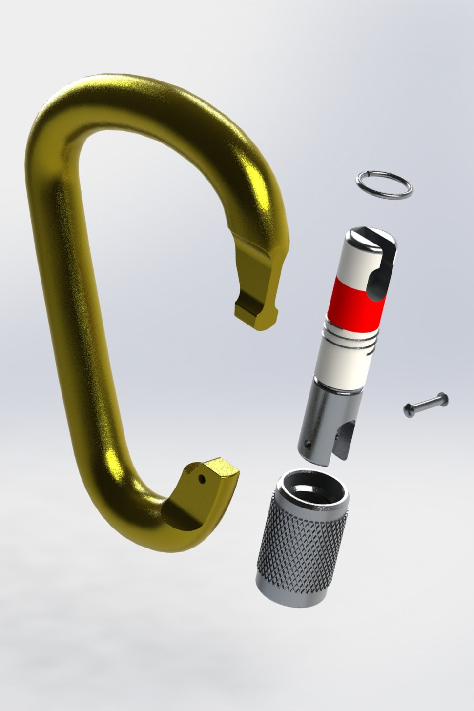
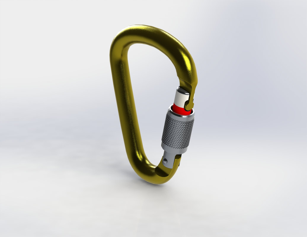
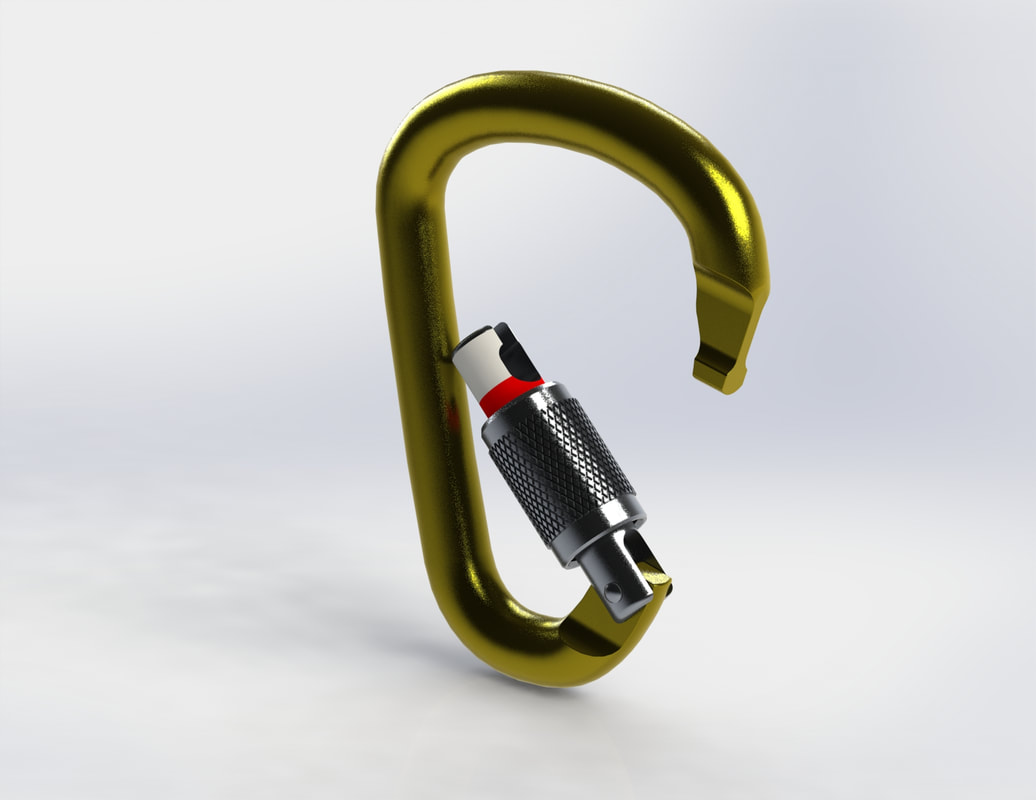
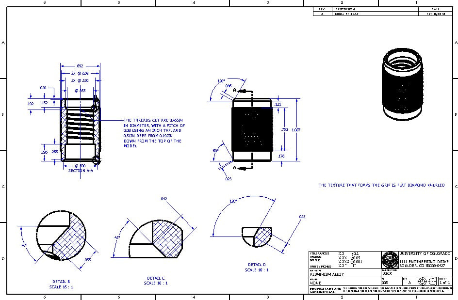
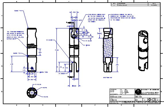
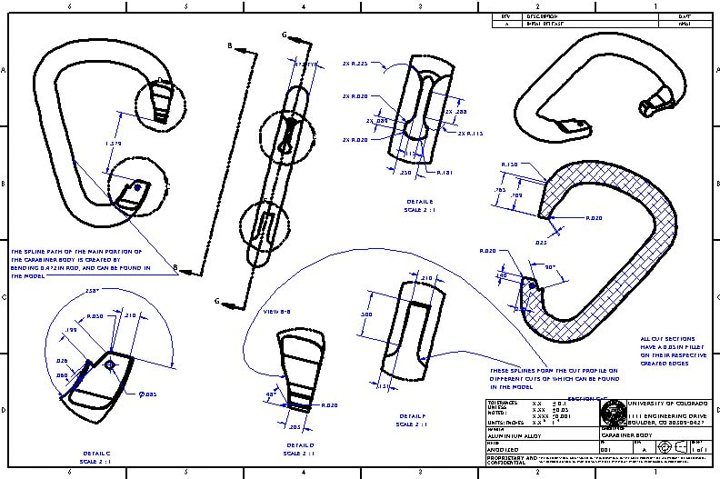
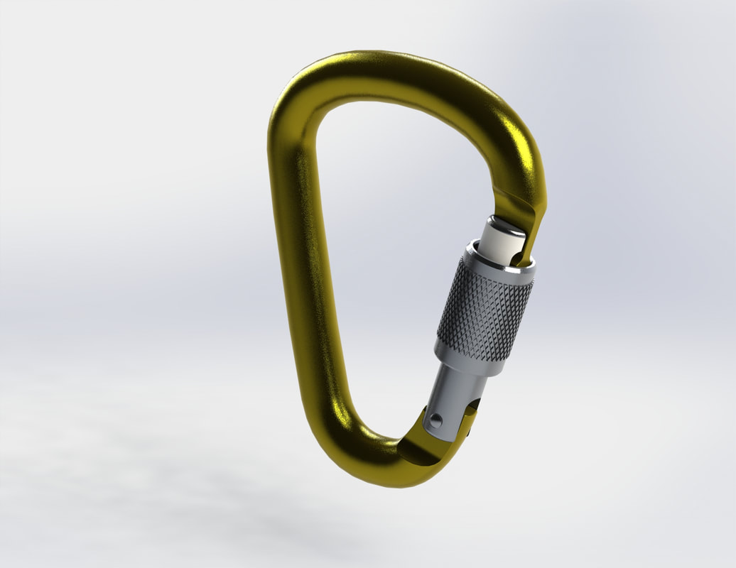
For our final project, each person was challenged to 3D model a multi component part (>3 pieces) from an existing part in the real world. I decided to model one of my climbing carabiners that I have as I thought it was an interesting object that I would be passionate about while doing this project. I was very happy with the final project as I felt that I modeled the part very well, and it just showed what I had accomplished through the entire class. Some challenges I faced were modeling some of the parts within the locking gate as I didn't want to take my carabiner apart, so I had to be creative with how I took my measurements. All in all, I felt I took a lot back from the course as a whole and it challenged me a lot.
ATLS 2300: TEXT
I took this class during the Spring 2020 semester and it was one of my favorite classes I had taken up to then. Text was just as much a class on typography and type structure as it was on graphic design, user experience, and society. The projects challenged me to take into consideration the principles of design from an aesthetic standpoint, but also to consider how the user would view and interact with whatever we were creating. The class had one lecture and recitation every week where we would go over topics and practice our skills. Recitations were helpful in particular as we got feedback from our peers.
Below are different projects:
Principles of Design


Abstracted Objectives
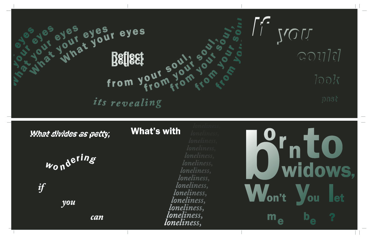
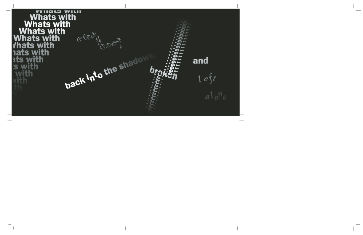
Expressive type
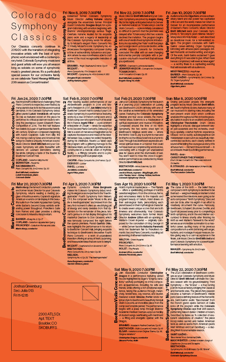
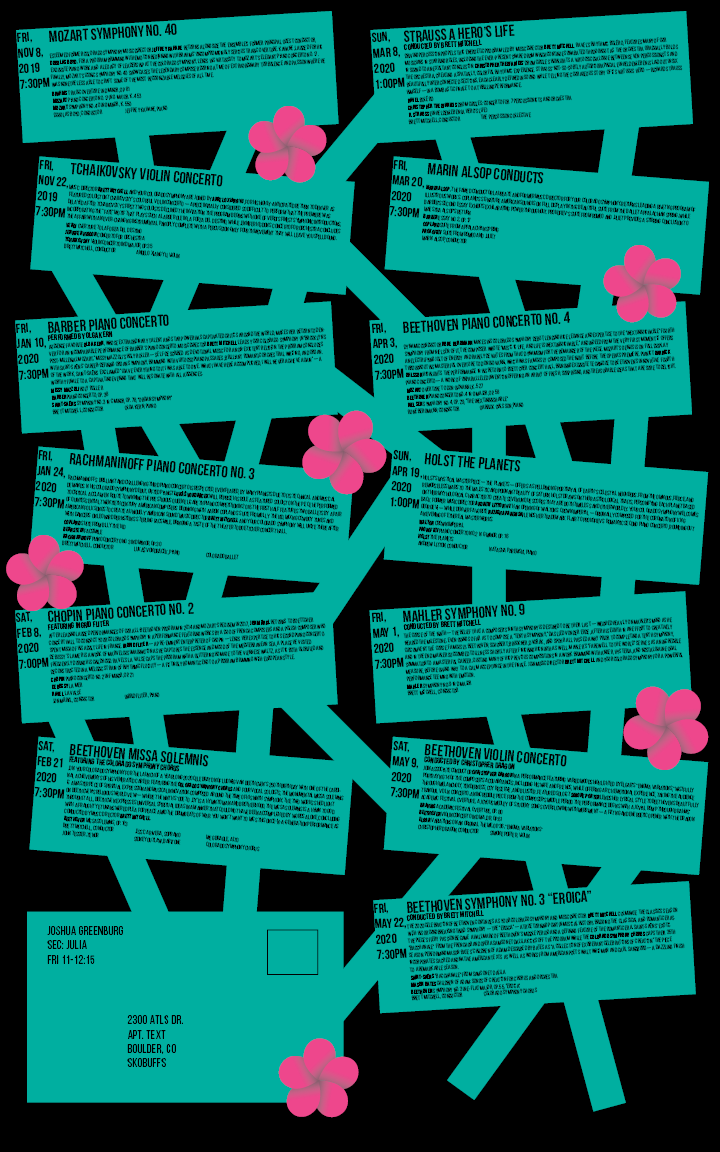
Type Specimen Poster
counterfeit design


Personal Logotype
tables of Death

project 1 expressive booklet
project 2 poster mailer


project 3 interactive infographic
ATLS 3300: Object
Below is the weekly blog for ATLS 3300 Object which I took during the Spring 2021 semester.
Lab 1 - Basic Electronics
Initial Setup:
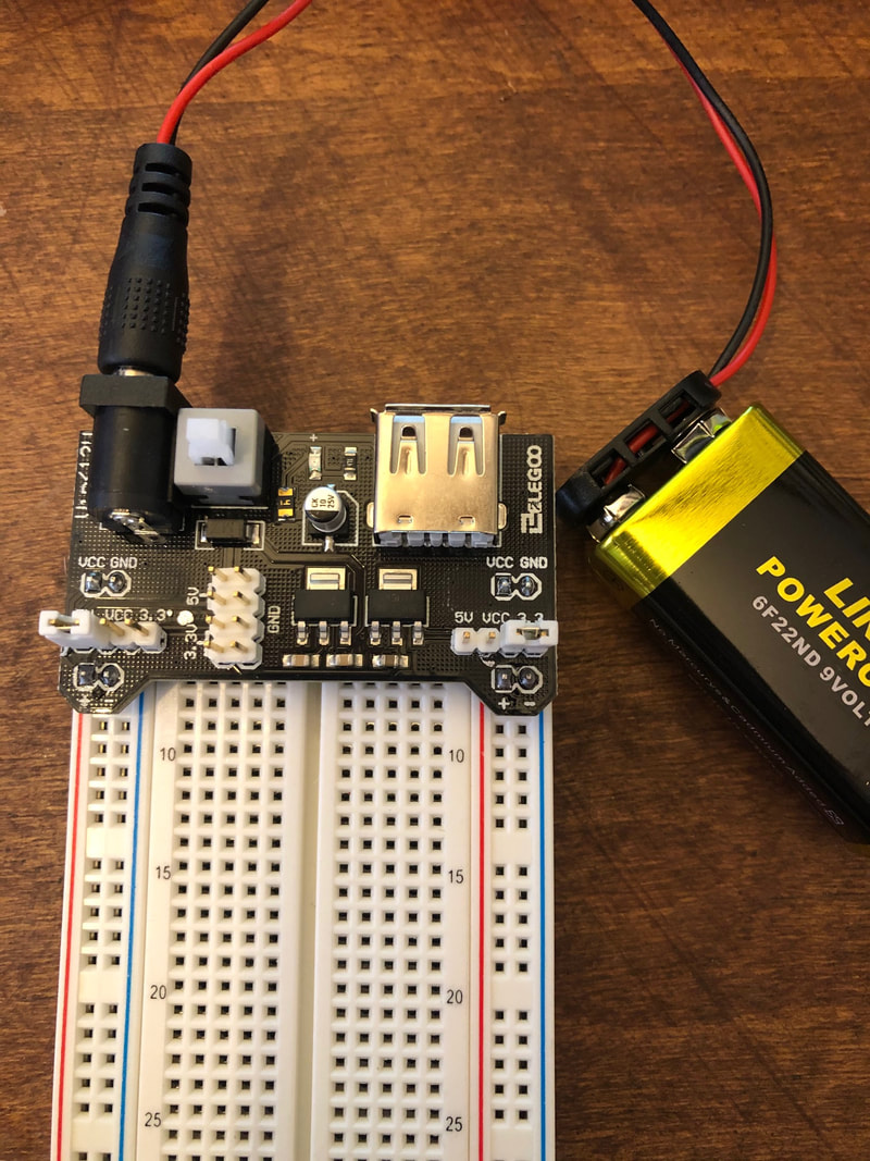
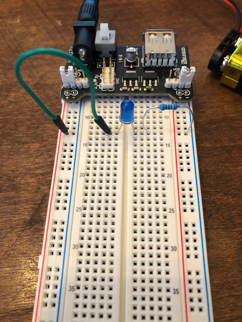
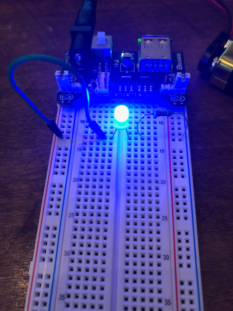
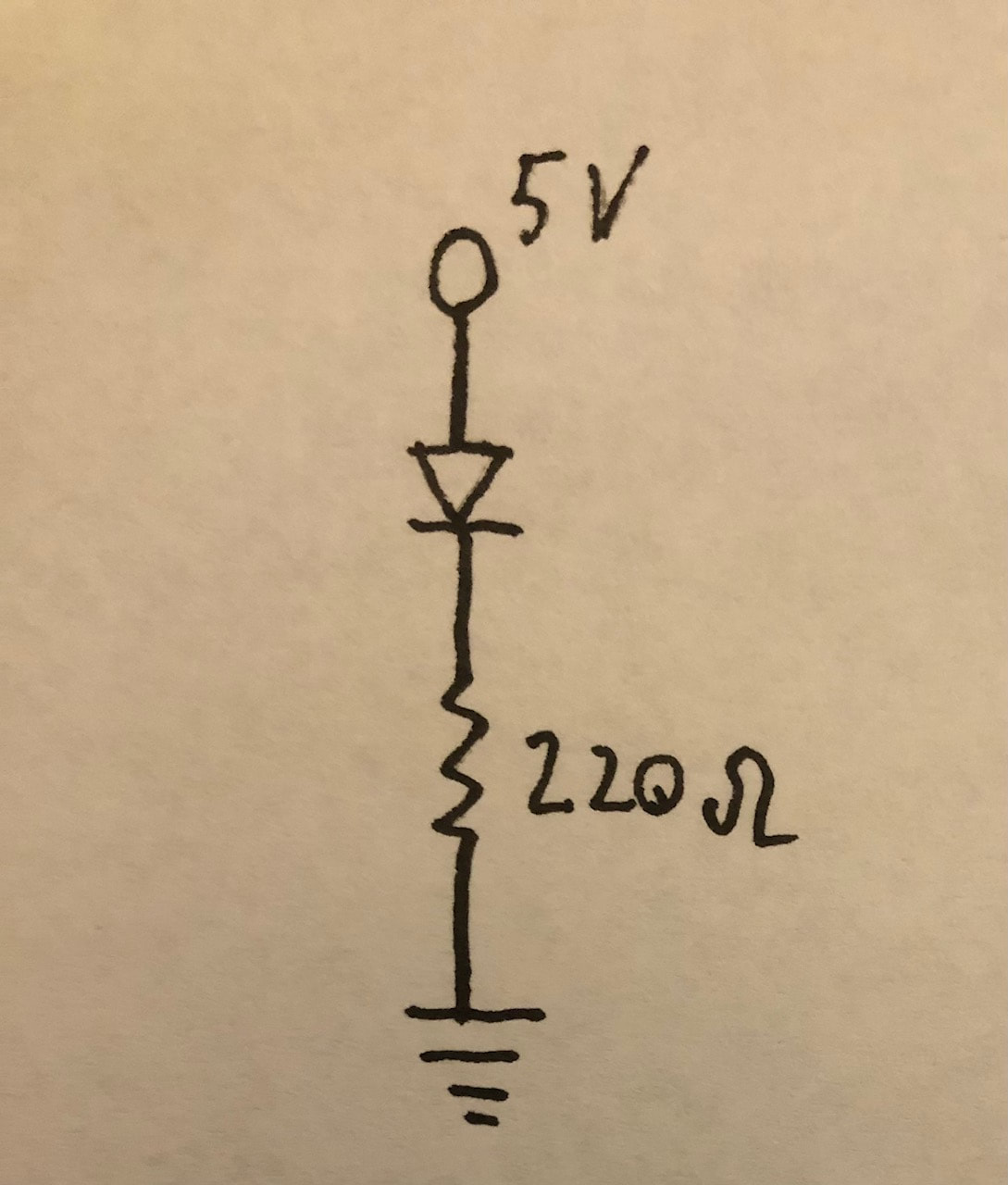
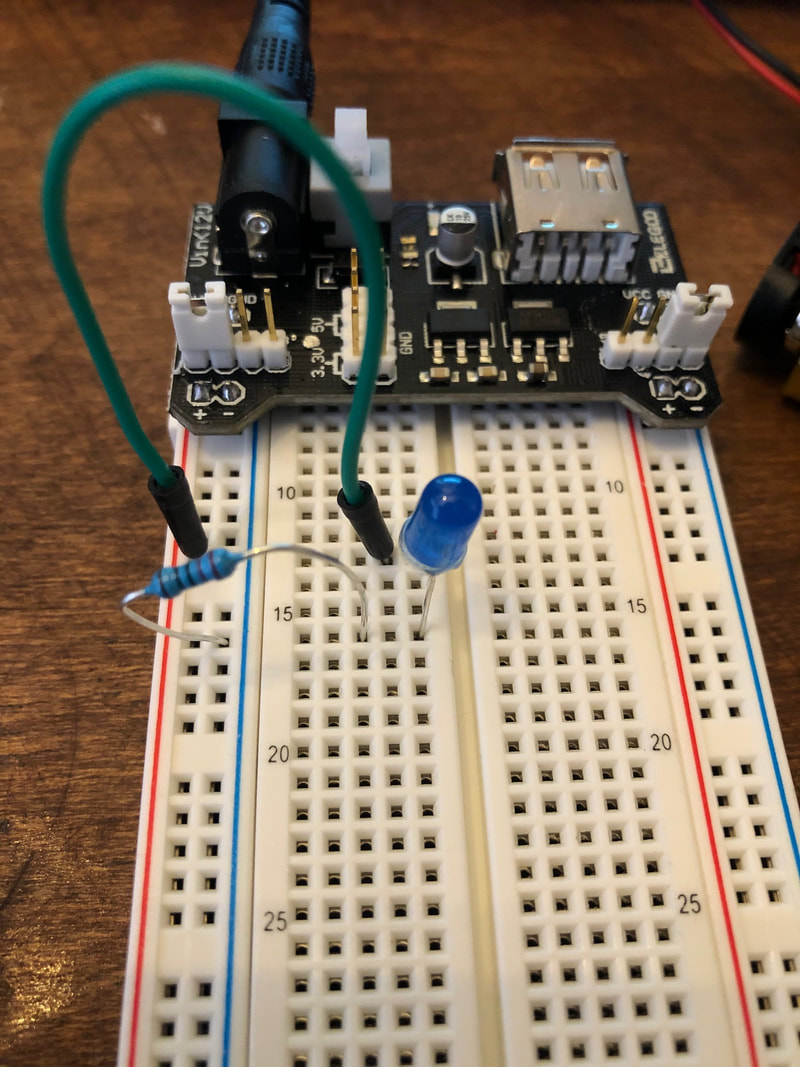
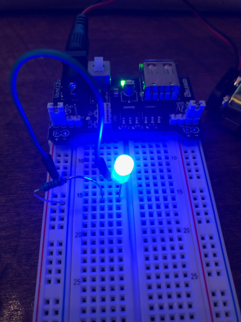
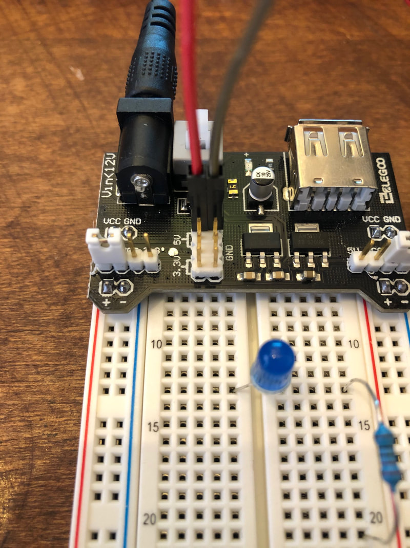
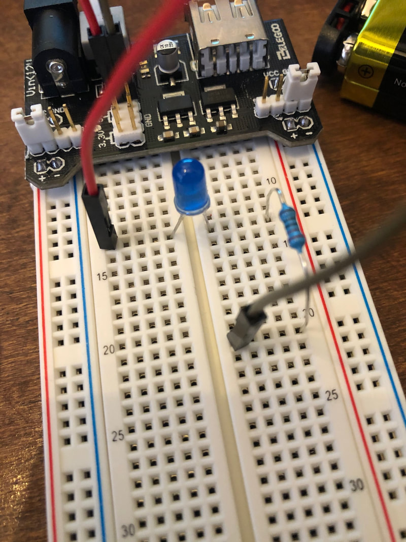
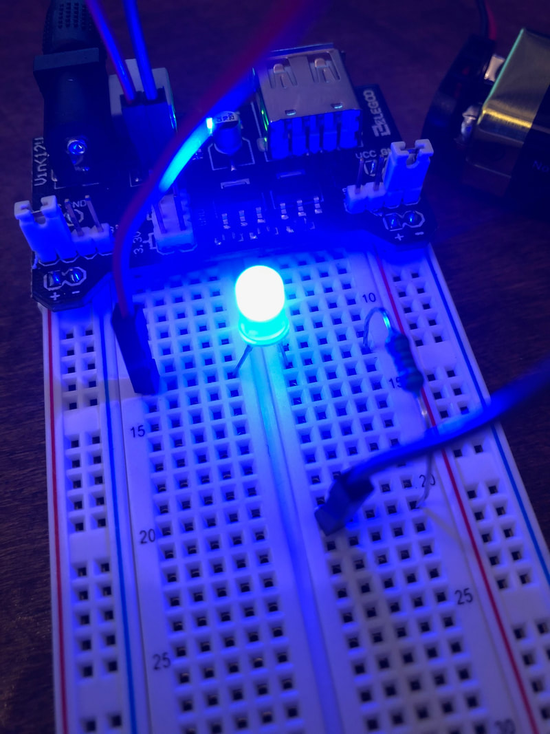
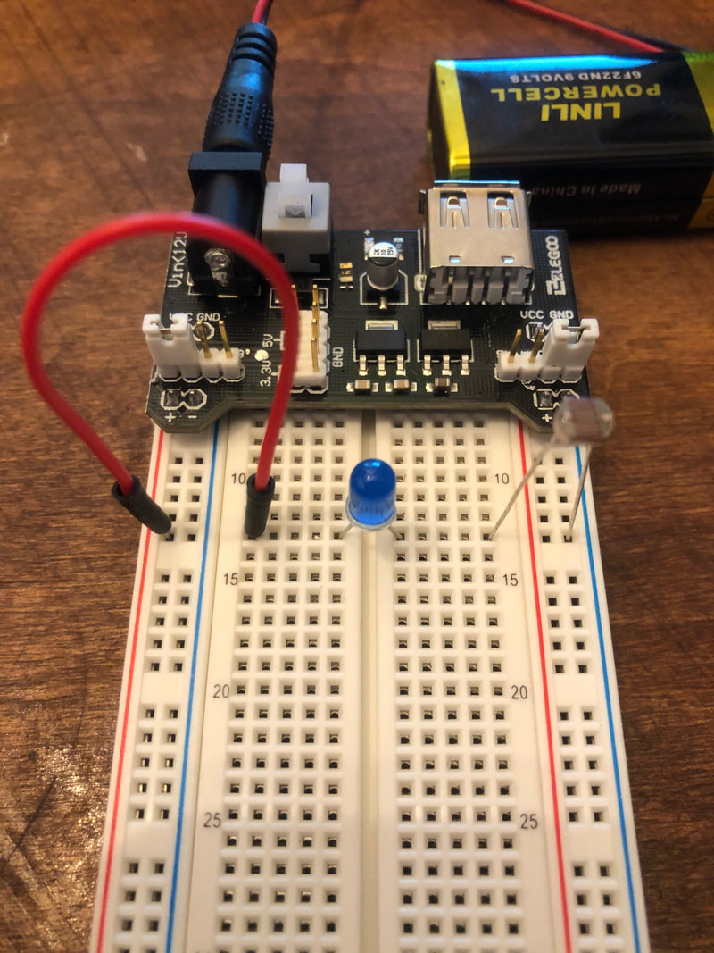
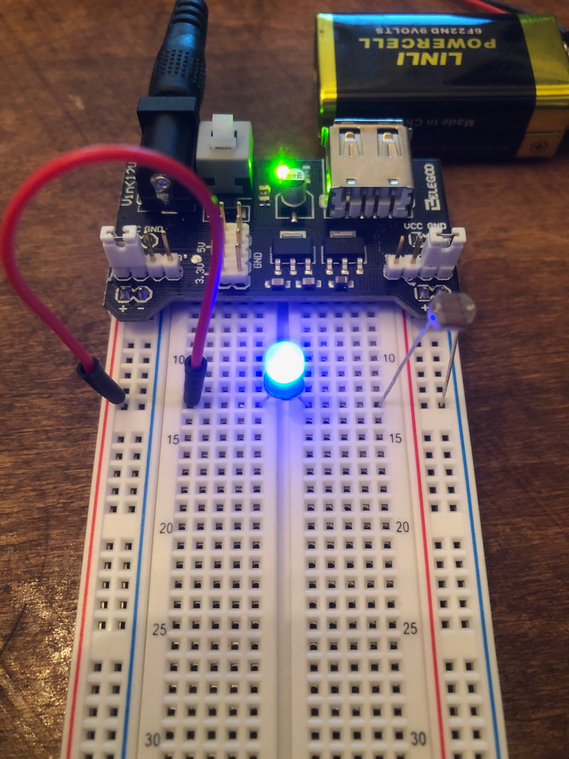
Initially we set up the board using a power supply module which fit nicely on the bread board. It allowed the power rails to be supplied with voltage and ground powered by the 9V battery. We set up a very simple circuit with an LED and a 220 Ohm resistor (see schematic above) that lit up the LED.
Alternate Setups:
We then did an alternative setup which was the same as the schematic in the Initial Setup.
Again we did yet another setup which was exactly the same except it utilized the power supply prongs that were directly on the power supply module.
Resistor Experimentation:
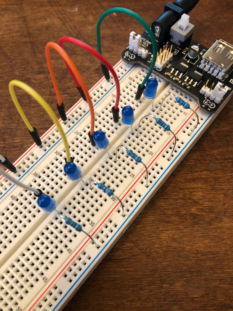
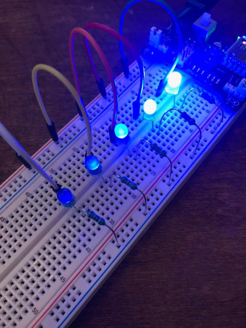
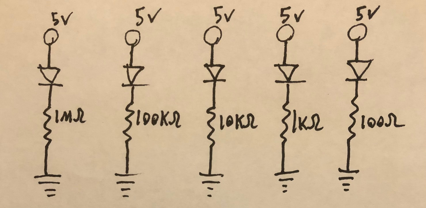
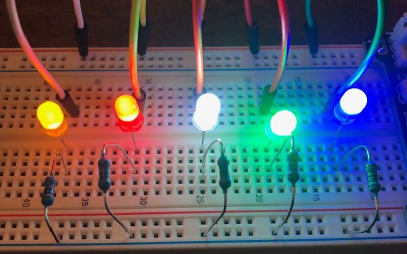
We then tested using different resistor values to see their effect on the LED brightness. As you can see above, using resistors values of 100, 1K, 10K, 100K, 1M Ohm, the brightness decreases respectively (see above for schematic). this is because the larger resistor values cause less current to flow (I = V/R) resulting in less light produced in the LED.
Adding Input:
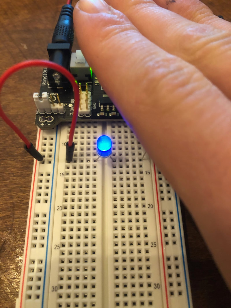
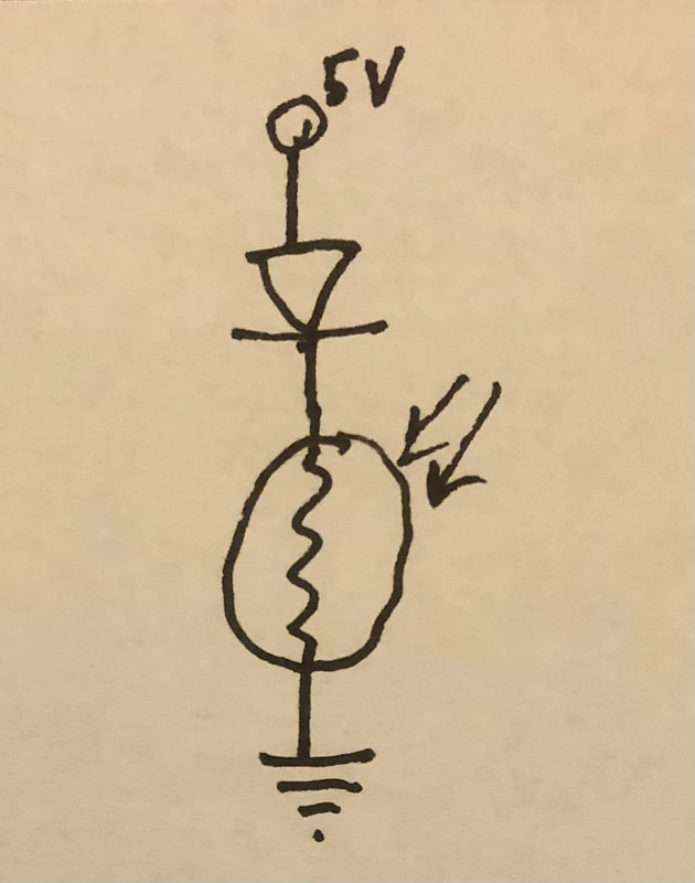
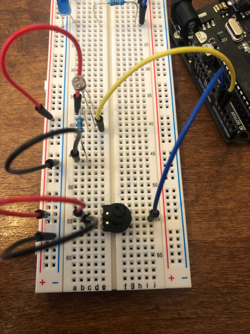
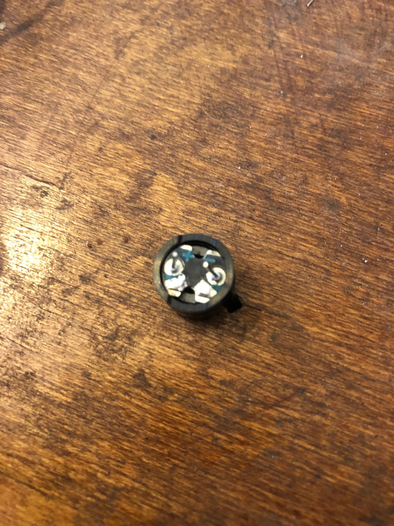
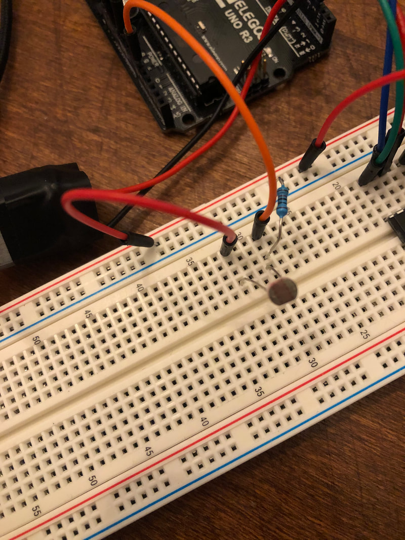
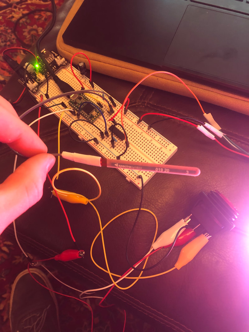
We added some input to control the brightness of the LED. First we used a photo resistor which changes resistance dependent on the level of ambient light. From our circuit (see photos and schematic above) you can see that the brightness goes down as the photo resistor is covered by my hand. This is because the resistance of the photo resistor goes up causing less current to flow (I = V/R).
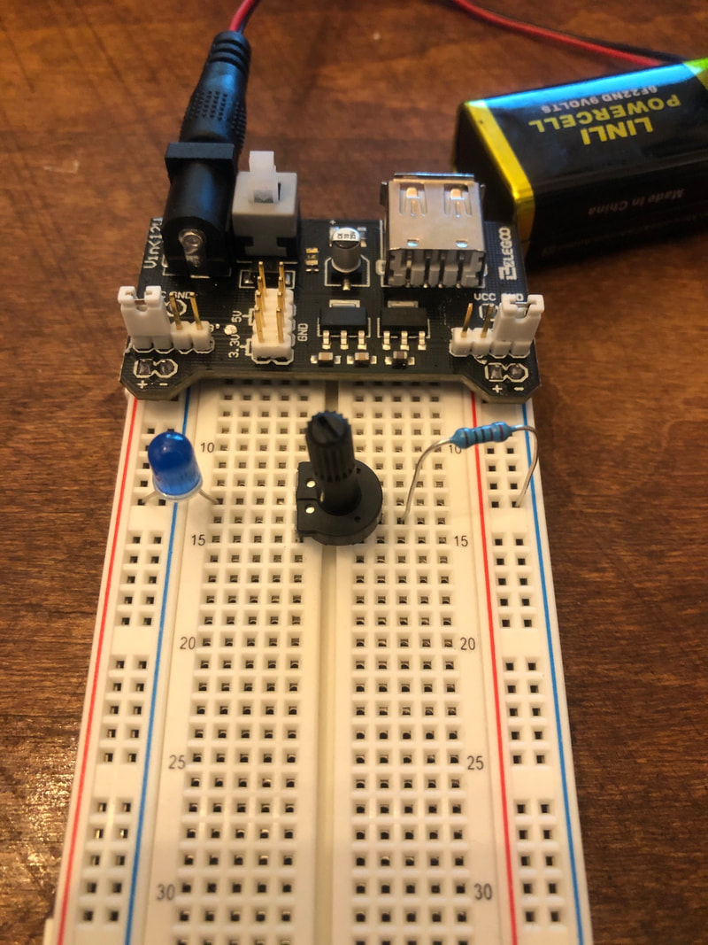
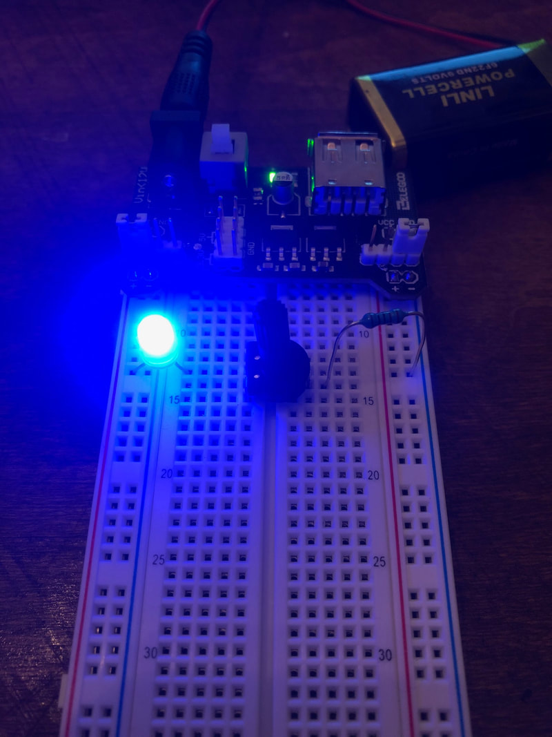
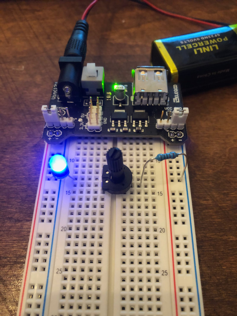
Finally we used a potentiometer to control the brightness of the LED. By turning the potentiometer, you vary the resistance in the circuit (see schematic above): All the way counterclockwise you have 220 Ohms from just the resistor (brighter), All the way clockwise you have 10220 Ohms (less bright).
Lab 2 - electronics continued
LEDs in Series and Parallel:
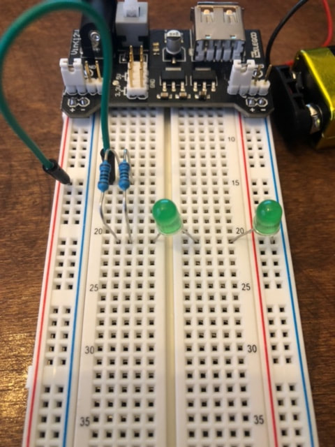
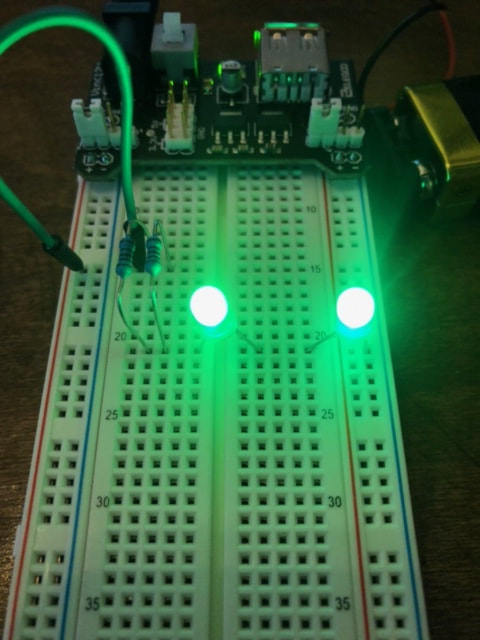
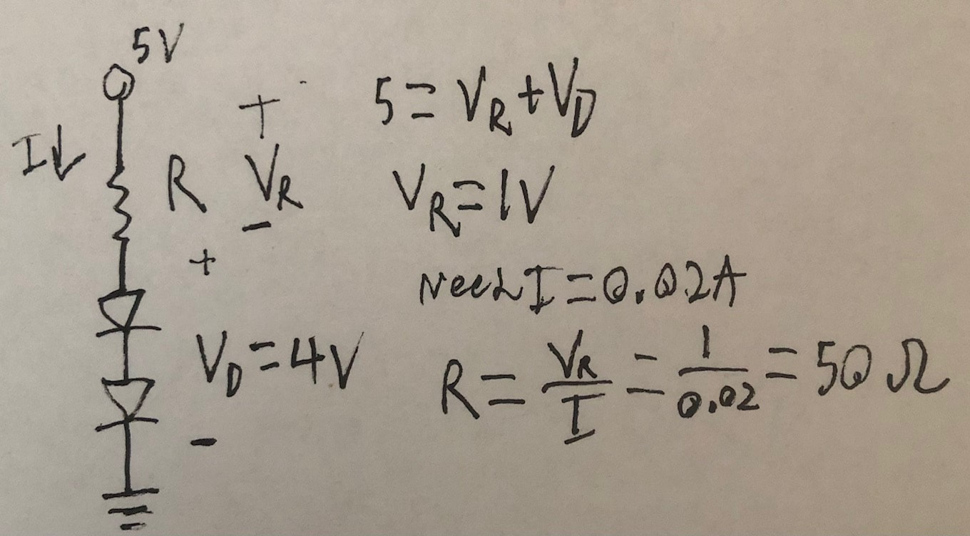
First we put LEDs in series. Because an LED requires 20mA and results in a voltage drop of 2V (per LED), we used this information combined with Ohms law to calculate the required resistor value of 50 Ohms, which is comprised of two 100 Ohm resistors in parallel (see above for schematic and calculations).
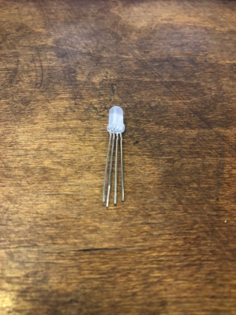
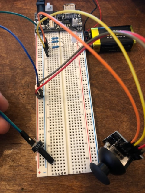
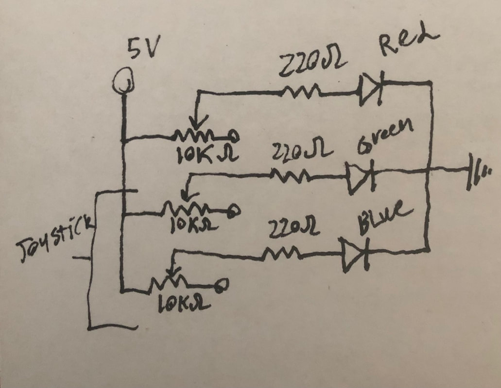
We then used LEDs in parallel. We did this with an RGB LED which is essentially 3 LEDs with a common ground(longest lead) in one bulb(see above). Because the LEDs are in parallel, their voltage drop in relation to the resistor is as if they were alone, so we used 3 220 Ohm resistors for each LED lead. We then connected the red lead to a potentiometer and the green and blue leads to the joystick(essentially two potentiometers. When the potentiometers are at full resistance, the current to the LED is lowered and so the LED is off, when the potentiometer is at low resistance, the LED only has 220 Ohms in series and so it is at full brightness. Varying the potentiometers changes the brightness of the LEDs causing different colors. See below for a video of this and above for a schematic and a photo of the setup.
Resistors in Series:
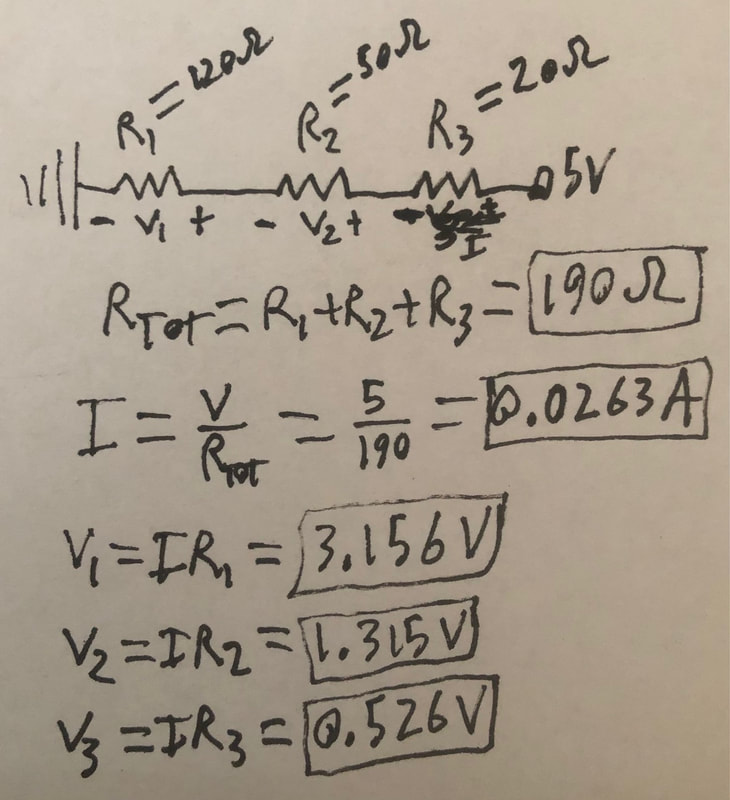
When you connect resistors in series, you find the total resistance by summing the resistances. with this information we can find the current and the voltage drop over each resistor using Ohms law.
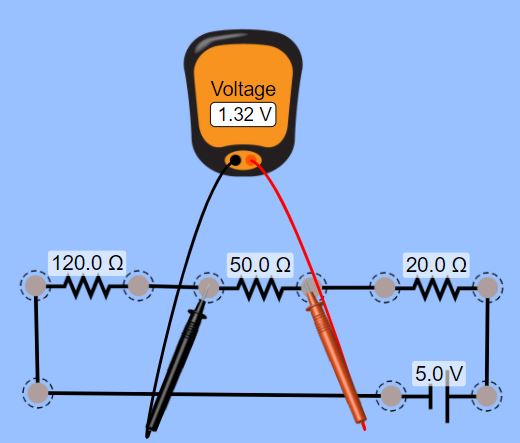
Resistors in Parallel:
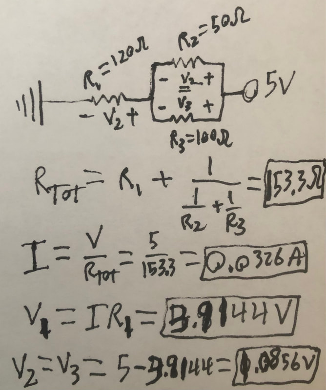
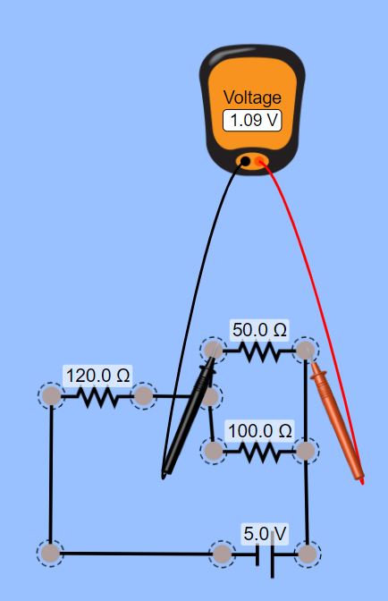
When you connect resistors in parallel, you find the total resistance doing one over the sum of the reciprocals of the resistor values. with this information we can find the current and the voltage drop over resistor one using Ohms law. We can then find the voltage drop over resistors two and three by using KVL and the fact that parallel resistors have the same voltage drop.
Arduino Installation:
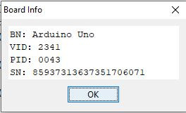
Finally we connected our Arduino and set it up with the program. Above you can see the "Board Info", we will use it more next week.
Lab 3 - Arduino and Digital i/o
Part 1: Digital I/O Circuit
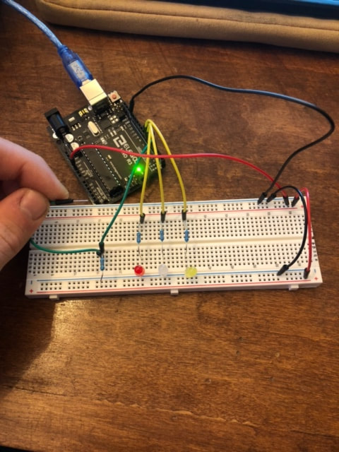
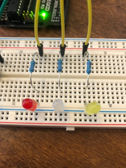
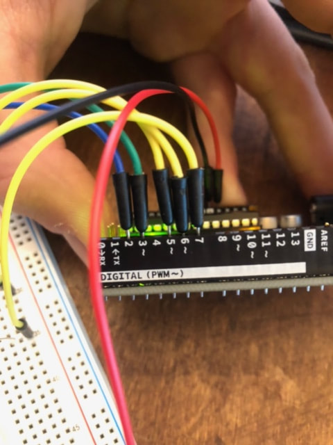
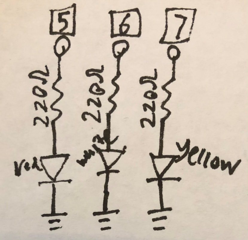
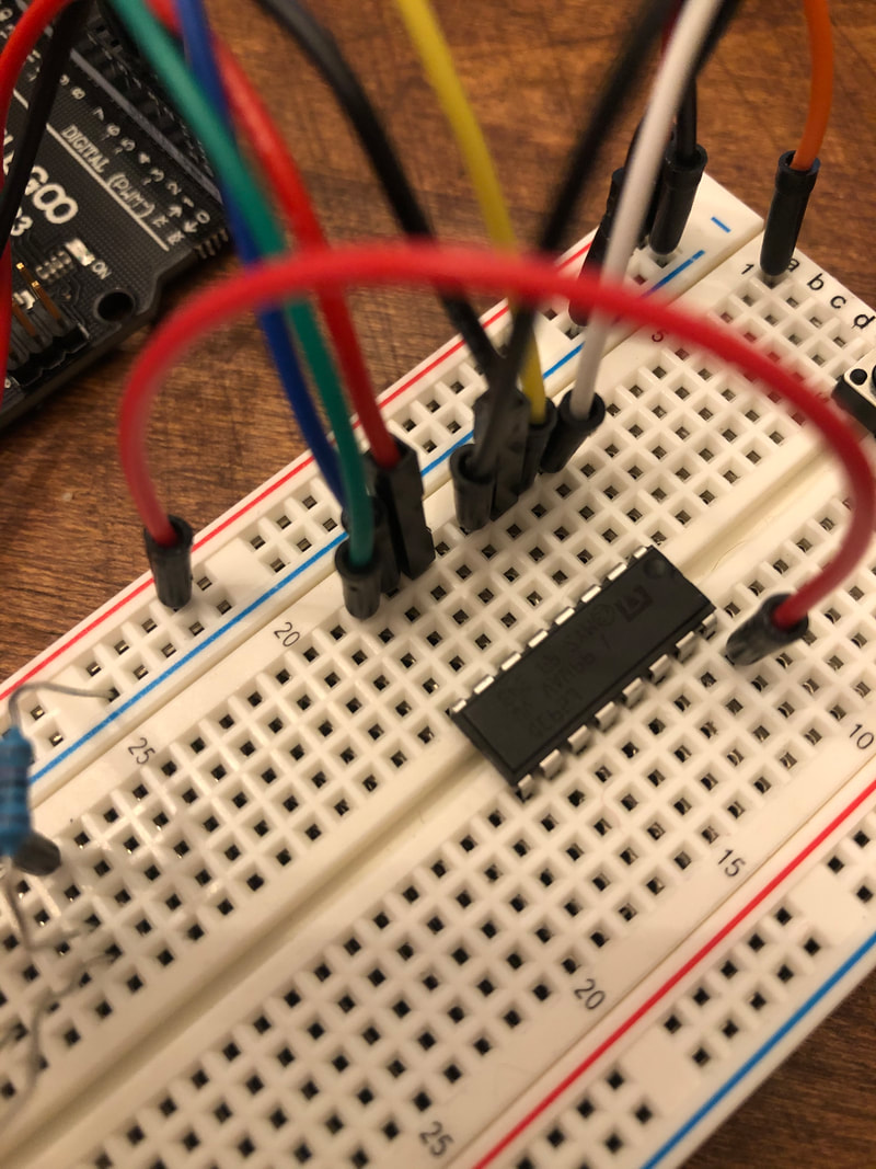
In this lab, we worked with input and output pins with the Arduino. as you can see in the circuit above there are two parts. The first part are the LEDs which are connected to our output pins (yellow: 5,6,7) and to 220Ohm resistors. When we write the pins to be "HIGH", they light the LEDs and "LOW", they turn off.
The second part is the switch which is comprised of a "Pull-Down" 10K Ohm resistor. The way this circuit works is input pin 3 (Green) is initially connected to a resistor which is connected to ground. It is seeing a "LOW" signal. But when we connect the switch wire to the 5V on the board, the input pin sees a "HIGH" signal. We have it coded so when pin 3 sees a "HIGH" signal, the LEDs light up, and when it sees a "LOW" signal, the LEDs turn off.
The second part is the switch which is comprised of a "Pull-Down" 10K Ohm resistor. The way this circuit works is input pin 3 (Green) is initially connected to a resistor which is connected to ground. It is seeing a "LOW" signal. But when we connect the switch wire to the 5V on the board, the input pin sees a "HIGH" signal. We have it coded so when pin 3 sees a "HIGH" signal, the LEDs light up, and when it sees a "LOW" signal, the LEDs turn off.
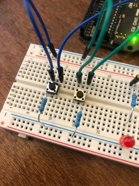
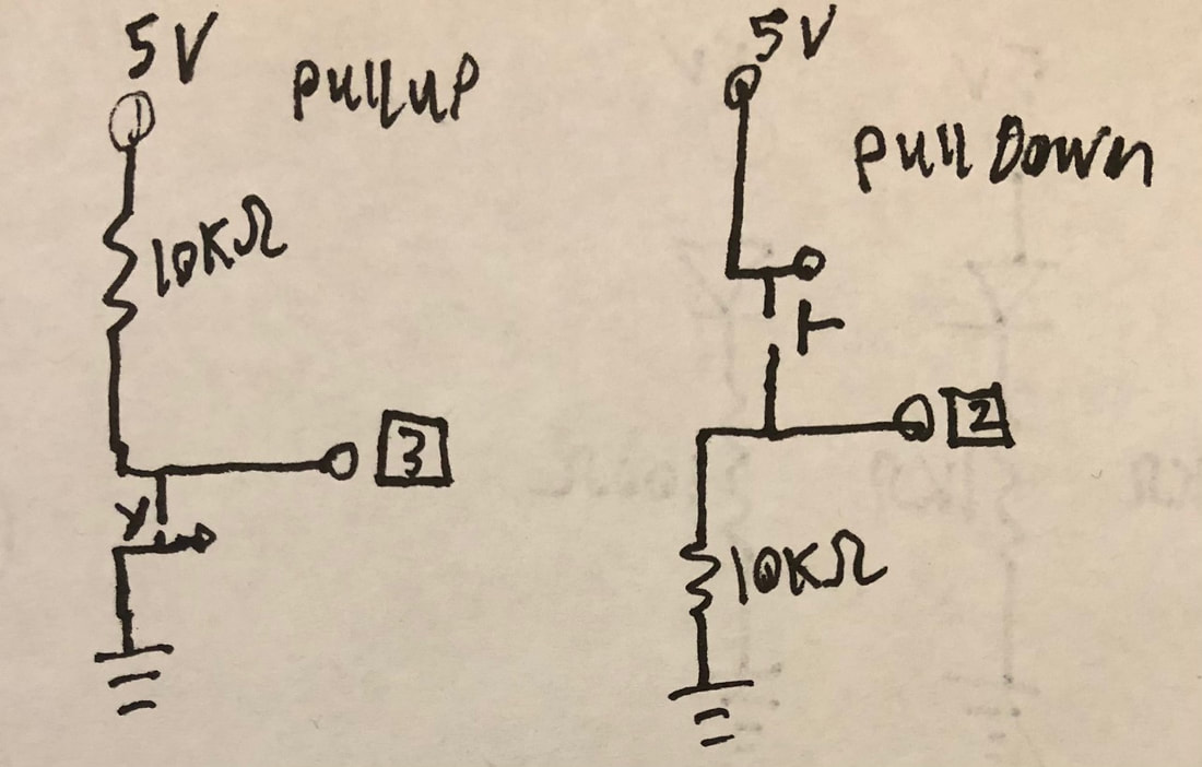
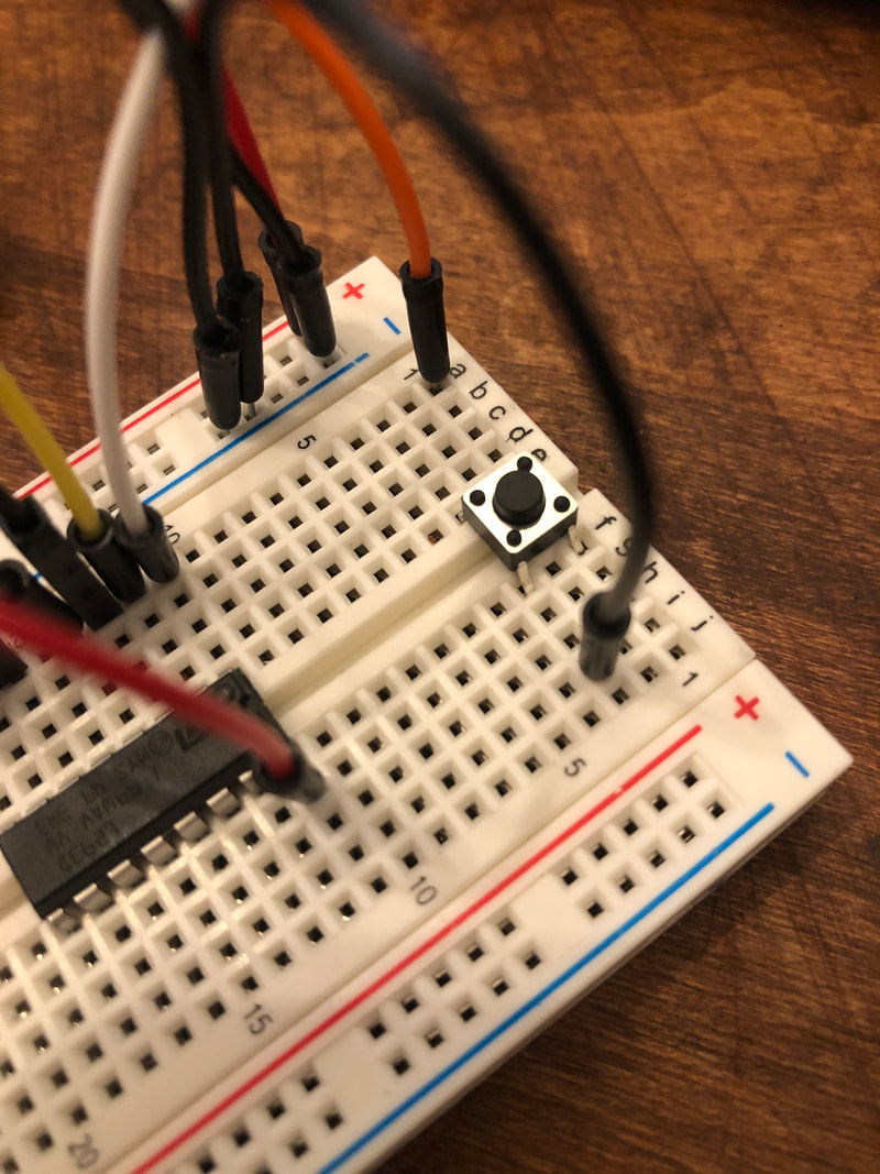
We then re-made the switch circuit using an actual switch. The Blue leads are the "Pull-Down" resistor circuit which is the same as described before now connected to input pin 2. The Green leads are a "Pull-Up" resistor circuit which works similar to the "Pull-Down" resistor. Initially the input pin 3 (Green) is connected to a resistor connected to 5V. It is seeing a "HIGH" signal. But when we hit the button, the pin is now connected to ground and so it sees a "LOW" signal. the way we have both circuits coded, when the pins see "LOW", the LEDs light up, and when they see "HIGH" the LEDs turn off. see above for schematics for the input and output.
We then worked within the Arduino coding language to have the LEDs flash in a pattern. we made it so that when the LEDs were turned on, they flashed in a pattern. We achieved this by using the "digitalWrite" and "delay" functions. See below for videos of the circuits and code.
We then worked within the Arduino coding language to have the LEDs flash in a pattern. we made it so that when the LEDs were turned on, they flashed in a pattern. We achieved this by using the "digitalWrite" and "delay" functions. See below for videos of the circuits and code.
Part 2: DIY Switch
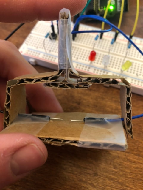
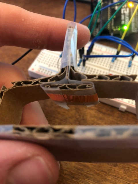
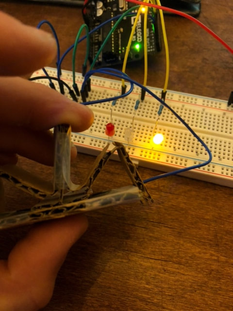
Above is my DIY switch. It is placed in the exact same spot as the "Pull-Up" resistor button and acts in the same way. It is made with cardboard, and flexes via strategic cuts to allow for a metal strip to contact two leads together. I designed it to spring back once pressure is let off of it.
The code and schematic for the circuit is the same exact one as used for the "Pull-Up with Pattern" (see above). See below for a video of the switch in action.
The code and schematic for the circuit is the same exact one as used for the "Pull-Up with Pattern" (see above). See below for a video of the switch in action.
Part 3: Creative Enclosure
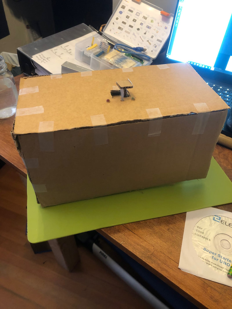
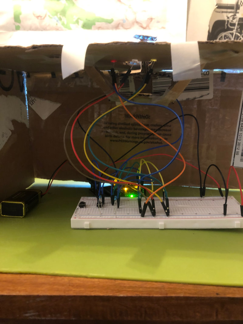
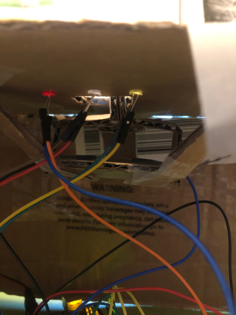
Using my switch, I added a flat piece at the top to make it sort of like a pressure plate. I then added longer female-male leads to the LEDs to extend them farther off the board. I then poked them through the top. I'm calling this device the "bud-Light", and it works by illuminating your drink when you place it down on the switch. See the video blow for the device in action.
Lab 4 - arduino analog i/o
Part 1: Analog Input & Output
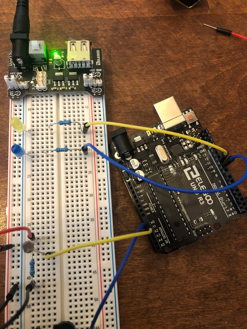
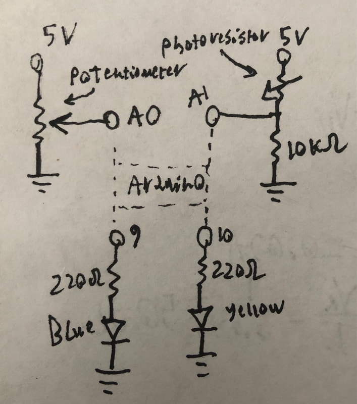
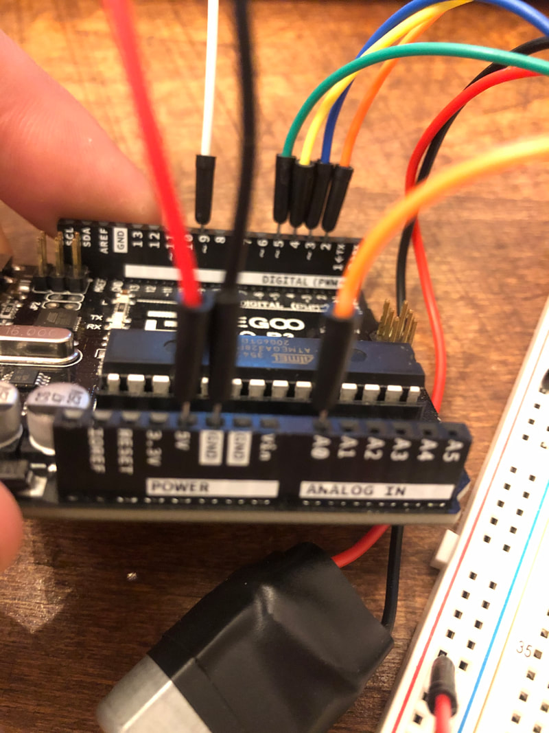
In this lab, we worked with the analog input and output capabilities of the Arduino. We started by creating two input circuits. The first was a potentiometer which had its slider connected to the analog input A0 (blue lead). The second was a photo resistor in series with a resistor and a lead to A1 which was placed in between the two (yellow lead). Both circuits act as voltage dividers, meaning that by changing the resistances on either side of the input, they change the voltage going to the input. With the potentiometer, the slider changes the resistance on either side of it by changing its position, and with the photoresistor, the light changes its resistance, changing the ratio of resistances on either side of the input. Both circuits output to pins 9 and 10 (blue and yellow) which connect to LEDs in series with resistors. See above for the circuits and schematics of both the inputs and outputs. Pins 9 and 10 are analog output pins meaning that they can output voltages between 0V and 5V unlike how the pins in the previous lab could only output either 0V or 5V. They achieve this using Pulse Width Modulation which is a way of altering square waves duty cycles in order to effectively represent different voltages using averages.
In terms of how the code works, well start with the input circuits. First, the input circuits send a voltage (between 0V and 5V) to the analog input pins depending on our physical input. the Arduino reads these voltages as a number between 0 and 1023 (because it has 10 bit resolution). We then map that signal to a number between 0 and 255 using the "map()" function as the output pins only have 8 bit resolution. that signal is sent to the output pins resulting in a voltage between 0V and 5V corresponding to our input, which changes the brightness of the LEDs. See below for videos of the circuit in action and the code.
In terms of how the code works, well start with the input circuits. First, the input circuits send a voltage (between 0V and 5V) to the analog input pins depending on our physical input. the Arduino reads these voltages as a number between 0 and 1023 (because it has 10 bit resolution). We then map that signal to a number between 0 and 255 using the "map()" function as the output pins only have 8 bit resolution. that signal is sent to the output pins resulting in a voltage between 0V and 5V corresponding to our input, which changes the brightness of the LEDs. See below for videos of the circuit in action and the code.
Part 2: Bonus Exercise
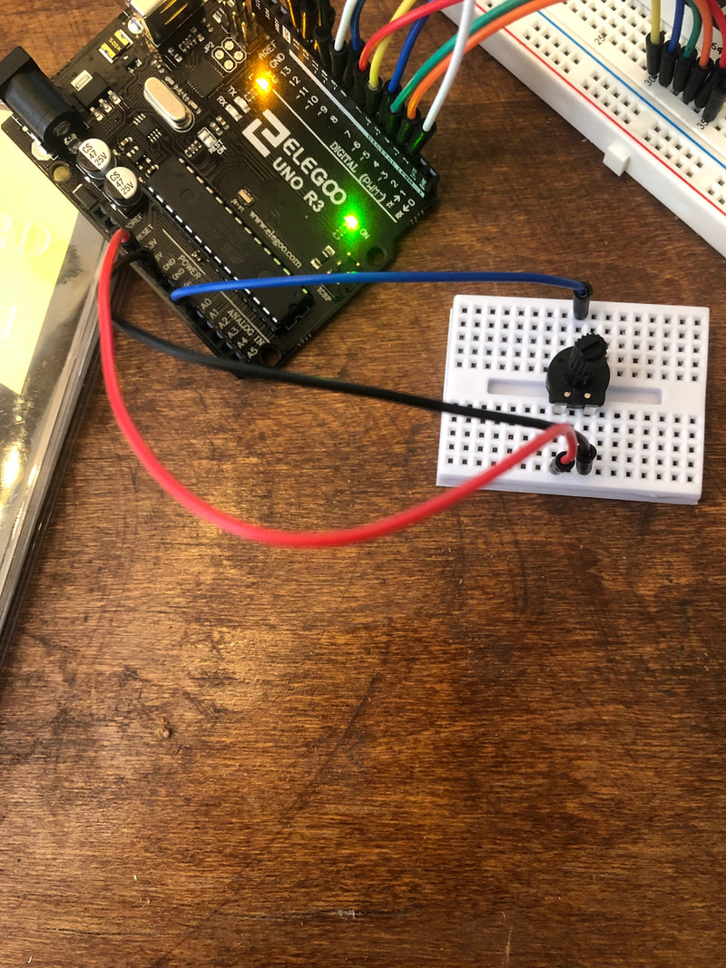
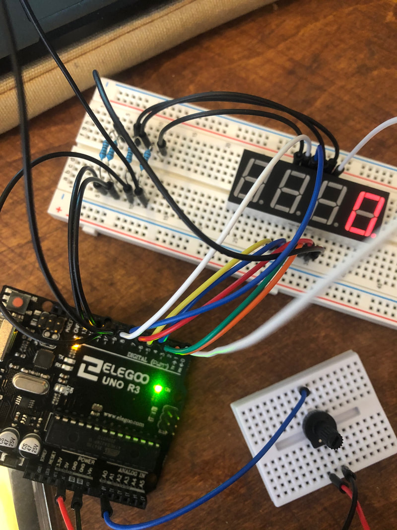
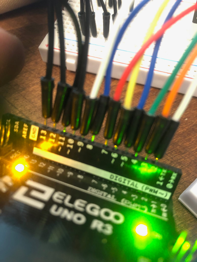
As a bonus, I wanted to see if I could get the 4 digit 7 segment display to display the input value from the potentiometer circuit. I've always wanted to use a 7 segment display so I was excited to try it out. I first started by moving the potentiometer to the mini breadboard to make some space for the rest of the circuit. Using a circuit diagram and modifying code from this source (How to Set up Seven Segment Displays on the Arduino - Circuit Basics), I was able to get the display to show the analog input from the potentiometer (between 0 and 1023). Essentially how it works is that pins 10, 11, 12, and 13 correspond to each digit (digit pins) and pins 2, 3, 4, 5, 6, 7, 8, and 9 correspond to each of the segments (and decimal point) (segment pins). On the back end, a file "SevSeg.h" (which I downloaded) is used to translate our number to the signals which alter the display. The digit pins are used to single out each digit for modification, and the segment pins are used to set the display number. See below for the code and the circuit in action.
Lab 5 - Build a musical instrument
Part 1: Tone Output
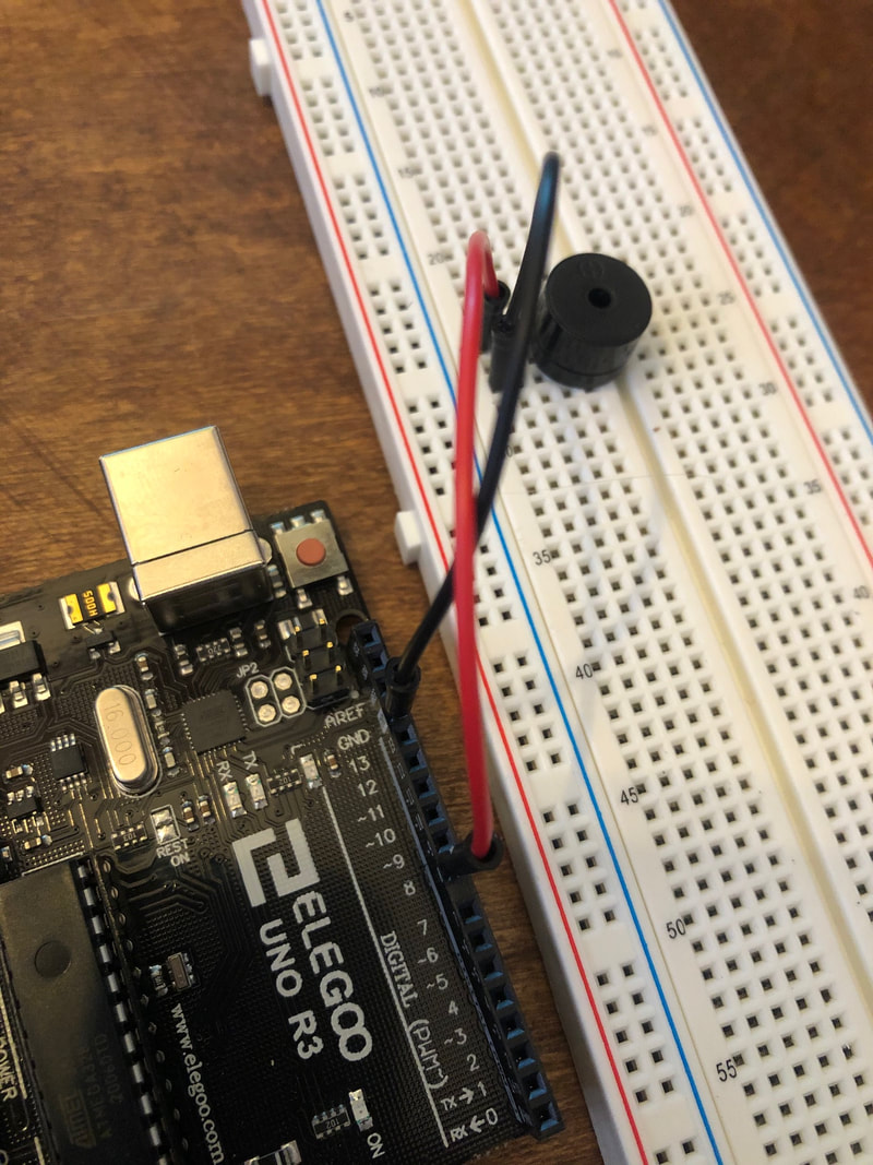
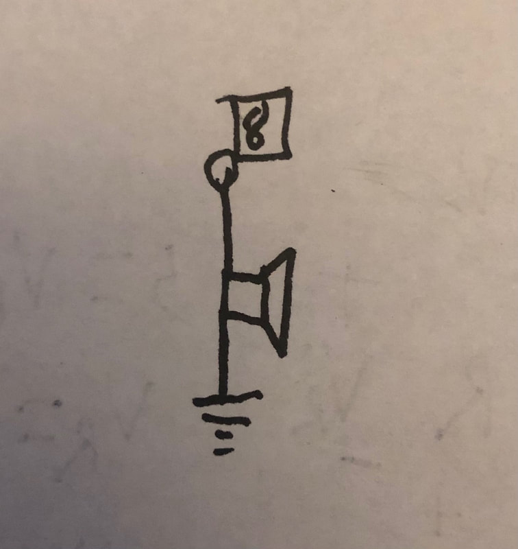
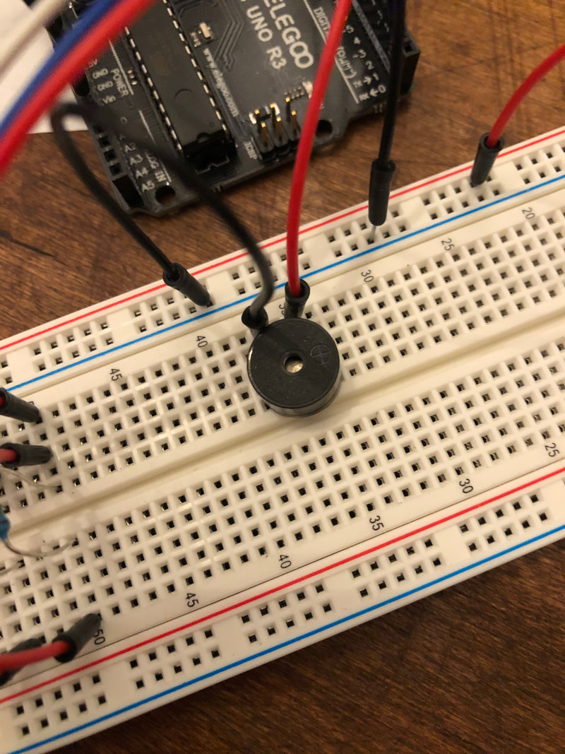
To start off, we created a very simple circuit using the passive buzzer. By setting pin 8 as the output, we were able to use the "tone()" and "delay()" functions to set the frequency and duration of tones. The higher the frequency the higher the tone pitch. As you can see in the code (and video) below, I made my buzzer play at 500Hz, 1000Hz, and 1500Hz each for a half second on a loop.
Part 2: Analog Sensor Input
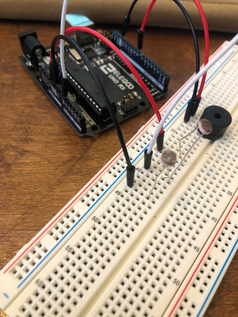
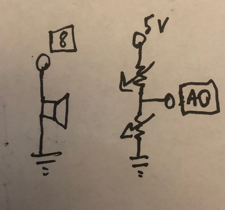
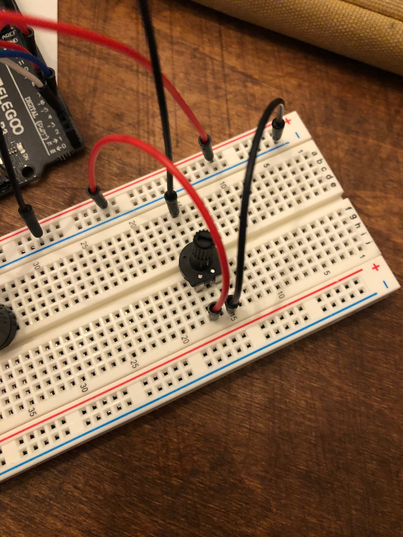
Next, we added some analog input to vary the buzzer sounds. We connected the A0 pin to the middle of two photoresistors (creating a voltage divider circuit). The value we read (using "analogread()") in A0 from covering the sensors in different ways was mapped (using "map()") to a value between 100 and 1000 to set the Hz value output (using "tone()") by our buzzer. See below for a demonstration of the circuit and the code.
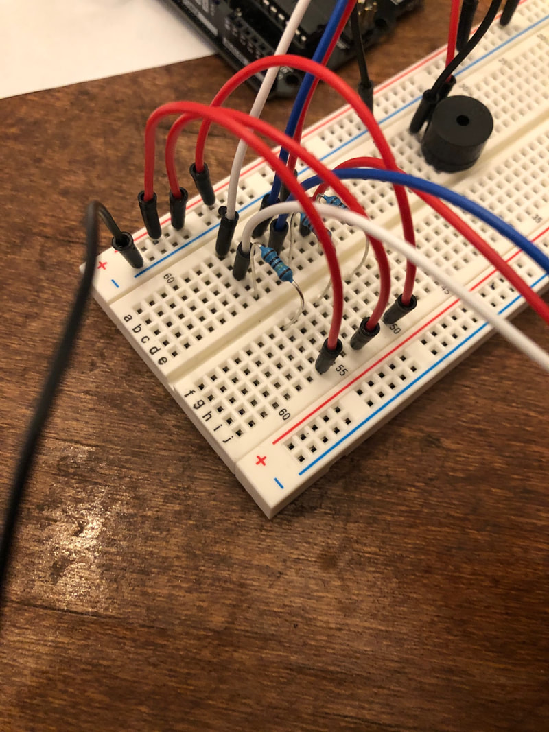
Part 3: Make a push-button piano
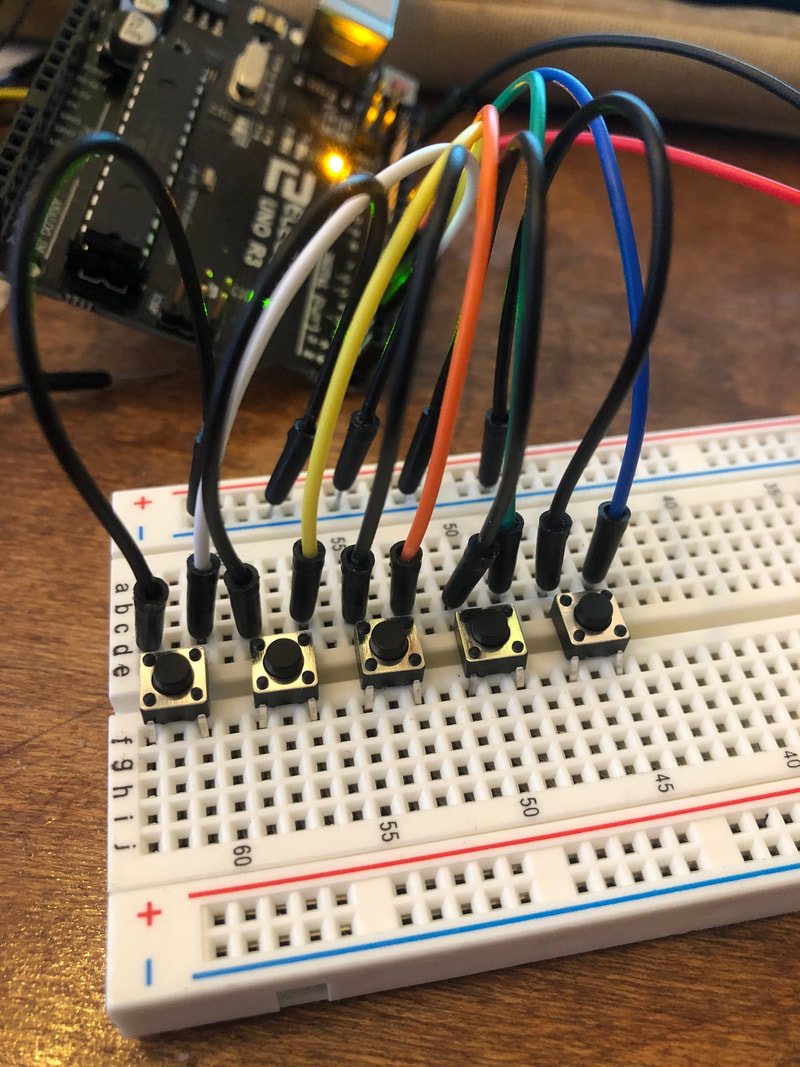
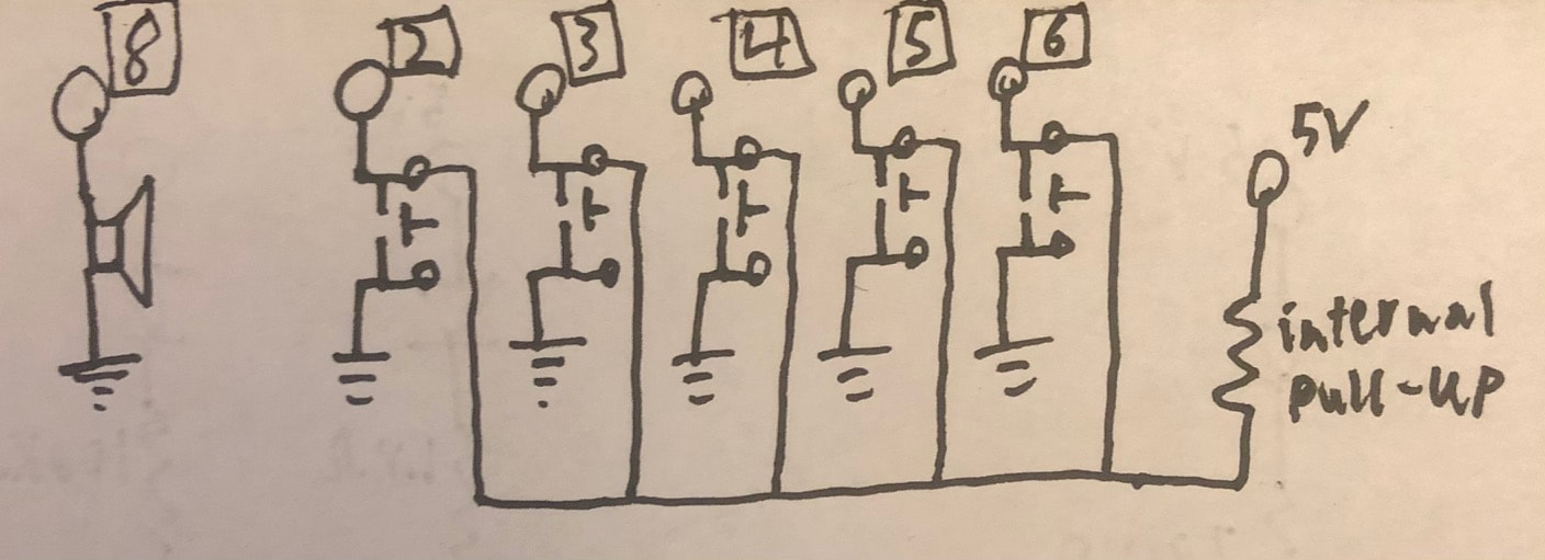
We then made a piano like circuit using push buttons. Each button (pins 2-6) were connected to digital pins using the internal pull-up resistor (done by using "INPUT_PULLUP" in the "pinmode()" function). I then used a "for loop" to loop through the buttons checking if they had been pressed. If they had, they would set a variable to 200*(button number+1). If multiple buttons were pressed at the same time, the highest number button would override the variable. After it checked all the buttons, it would set the buzzer to that Hz value and play the sound using "tone()". This means the buttons played at 600Hz, 800Hz, 1000Hz, 1200Hz, and 1400Hz. See below for the code, and a demonstration of "Taps" played on the piano.
Part 4: Create your own custom musical instrument
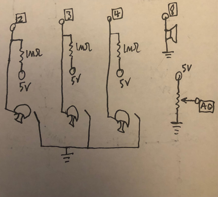
For the last part of the lab, we had to make a musical instrument. I saw a few examples online of people who used produce as sensors, and I thought mushrooms looked kind of like drums so I used those. Using code that I adapted from Banana Piano - Arduino Project Hub, I made a circuit that plays notes when you complete a grounded circuit (one hand on a ground pin, the other on the mushroom)(essentially a pull-up resistor circuit). It also features a potentiometer which adjusts the pitch set of the three notes (c1, d1 and e1 all the way to c7, d7 and e7) using a voltage divider circuit connected to A0. the way it works is a "for loop" checks the mushroom pins (2, 3, and 4) and if they are LOW (meaning that they are touched), it outputs a tone (determined by the potentiometer) to the buzzer (pin 8) using the "tone()" function. The potentiometer determines the row in a 2D array using the "map()" function, and the mushroom tapped determines the column. I should mention that I have "pitches.h" included and the array is filled with pitch values. Below you can see the code and a demonstration of my instrument I'm calling the "Portobello Player". Here is a link to the class discord post.
Lab 6 - serial game or arduino controller
Part 1 - Interactive P5.JS Scene
First, we started by creating basic shapes and changing different elements within P5.JS. You can find my code here for the static image below. Essentially what I did was make a "squareBlock" object which held information on the x and y position, width, and roundness of a block and had a "display" function which makes a square on the canvas. In the setup, I add block objects to an array and arrange them in a square grid. I vary the roundness based on where on the grid the blocks are. The draw loop just draws the background and calls the display function for each block.
We then added interactivity to the sketch. I wanted to keep the same basic form that I had in the static sketch so I copied over the code (which you can find here). The only difference with this sketch is that I give the "squareBlock" object a color attribute, and I also add a "change" function. The way this function works is that It first calculates the distance from the mouse to the center of the square using the distance formula. I then change the roundness of the square (more round if closer, less round if farther away). I then change the color of the square using "map" (closer, the color goes to the background grey, farther and it goes to white). This is called for each square in the draw loop which also displays each square.
The effect is this really cool interactive panel (see below) which gives the illusion that the mouse is depressing the square array.
The effect is this really cool interactive panel (see below) which gives the illusion that the mouse is depressing the square array.
I then made another interactive sketch just because I was feeling inspired (find the code here). It uses the same basic structure as the block sketch, except instead of blocks, it uses lines. The "lineBlock" object takes an x and y position, a width, and an x and y spread which help determine the spread of the lines in those directions. The "change" function works by first calculating the slope and distance of the imaginary line between the mouse and the center of the line block. It then takes converts the distance to a mapped value and creates a "size" variable based on e^x. It finally sets the x and y spreads to the "size" times the respective x and y components of the slope. The spreads are used later in the display function to form the line.
The result is a vector field like display. The lines face the cursor and dwindle in size exponentially as the get farther away.
The result is a vector field like display. The lines face the cursor and dwindle in size exponentially as the get farther away.
Part 2 - P5.JS <-> Arduino Serial Communication
To make our P5JS scene controlled by an outside source other than our computer, there were a few steps involved:
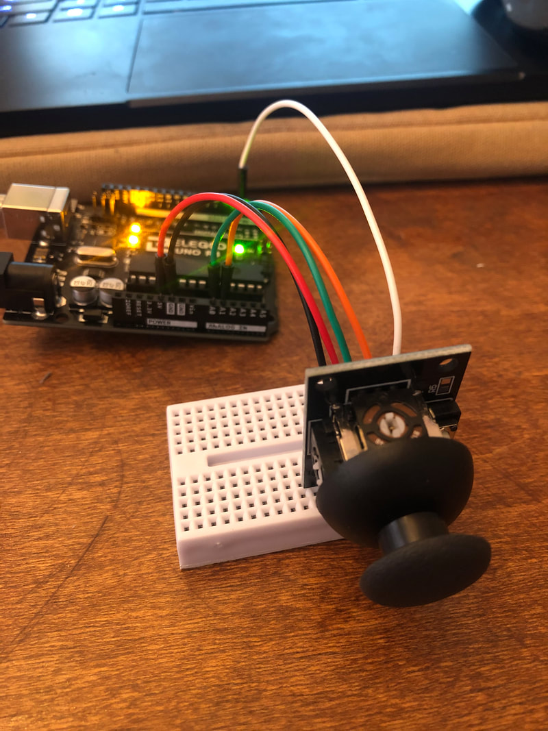
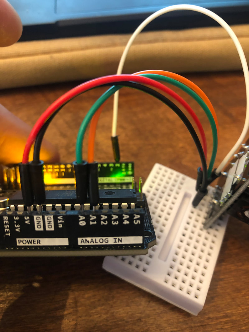
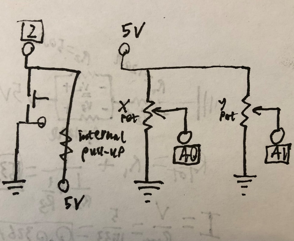
The first is to set up the Arduino circuit and code to take sensor inputs. I used the joystick (3 sensors in one easy to use device) with 5V and ground connected, and wires going from the two potentiometers and the click button (A0-green:xPot, A1-orange:yPot, 2-white:button) (see diagram and photos above). With the code (see below), I took the analog values read by the potentiometers (A0,A1) and the digital value read by the button (pin 2 with input pull up), and stored them as variables. I then mapped the analog values to a smaller range using the "map()" function. I then used "Serial.print()" with my sensor values and commas to send my sensor data out in a way that P5JS can read it. it would look like this for example:
111,123,1
The data then gets sent to P5JS through this program that we downloaded called "P5 Serial Control". We open the Arduino port within the program and make sure that it is sending ASCII values.
Within P5JS we used the template provided in class created by Arielle Hein. In order to read the data being sent from the Arduino, I edited the port name to be my Arduino port name (COM4). I then made some global variables to store my sensor inputs. Within the "serialEvent()" function definition, I read my output from the Arduino using "serial.readLine()" and split it using the "split()" function at each "," and set those numbers to equal my variables. From here, I copied my code from the square block sketch from part one, with the only changes being instead of the mouse position, I used the sensor position, and I made the colors invert in the "change()" function of the "squareBlock" class when you press the button. You can find my code here.
As you can see from the video below, The blocks change depending on the state of the joystick, and the colors invert when you press the button in. One thing that You may be able to notice is the fact that the roundness of the blocks don't change (which was not intended). I feel like I tried everything to remedy this, I used "console.log()" to check my variables, re-wrote my code structure numerous times, and changed variable names to no avail. I even hard coded the roundness of the blocks to a set number and it still didn't work (even thought console.log showed the values were not 0). This leads me to conclude that there must be something in the template which interferes with the "square()" primitive. The color does work, so in the end it does give off the same effect.
lab 7 - motors
Part 1: DC Motor Control
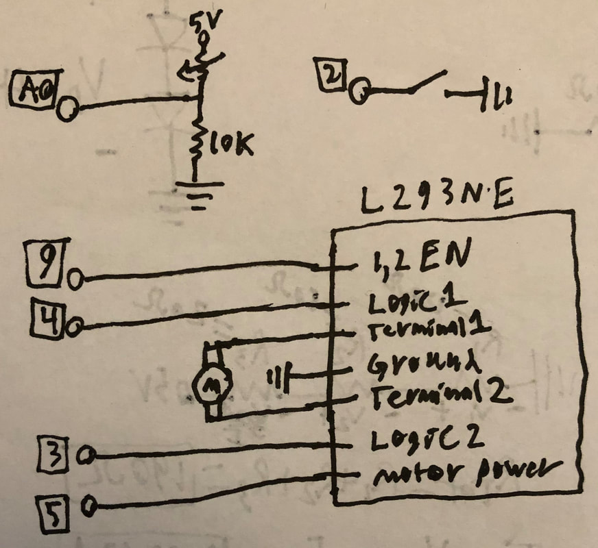
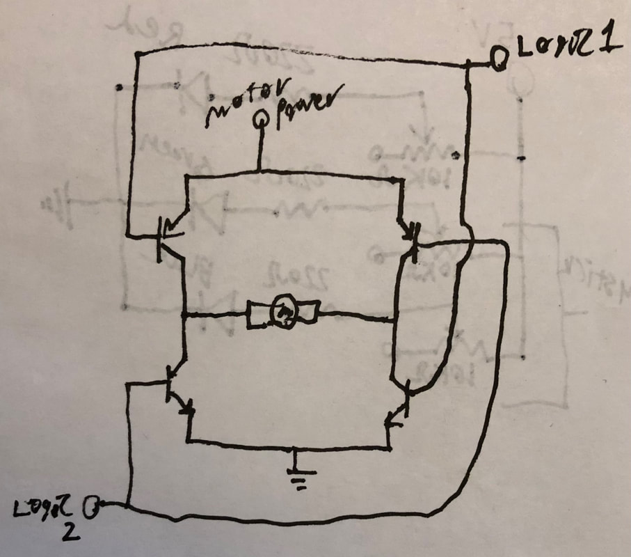
To start the lab, we created the motor circuit using the H-bridge (see above). We connected pin 9 to the H-bridge power, pin 4 to logic 1, pin 3 to logic 2, pin 5 to the motor power, the motor to the two terminals, and ground to ground. The way the H-bridge works is that it uses transistors to direct the flow of current to the motor. When logic 1 is High and logic 2 is Low, the motor spins in one direction and when it is flipped it spins the other direction. depending on whether it is High or Low, the transistors will either allow or prevent the motor power supply from flowing. See above for how the H-bright is configured internally.
Our inputs are a switch to pin 2 (using the internal pull up resistor), and a voltage divider using a photoresistor to pin A0. We start by detecting the signal to A0 and pin 2. Pin 2 will detect either 0 or 1 and depending on which one, we set the logic pins (3 and 4) to different values to set the direction of the motor. The value from A0 is mapped to a signal from 255 to 0 which is used with PWM to set the power output by pin 5. See code and video below. Essentially what happens is light increases the speed of the motor and holding the button down or up changes the motor direction.
Our inputs are a switch to pin 2 (using the internal pull up resistor), and a voltage divider using a photoresistor to pin A0. We start by detecting the signal to A0 and pin 2. Pin 2 will detect either 0 or 1 and depending on which one, we set the logic pins (3 and 4) to different values to set the direction of the motor. The value from A0 is mapped to a signal from 255 to 0 which is used with PWM to set the power output by pin 5. See code and video below. Essentially what happens is light increases the speed of the motor and holding the button down or up changes the motor direction.
Part 2: Serial Communication: Control Motor over Serial
For the second part, we wrote code to control the motor over serial communication with a P5.JS sketch. Circuit wise, It was the exact same as in part one minus the button and the photoresistor voltage divider. Code wise for the Arduino it also was the same with some modifications. in the loop() function, we first check in a while loop "Serial.available()" which returns if there is information to be read in the serial input. Within this, I read the two integers that I pass from P5.JS using "Serial.parseInt()" and store them as "speedData" and "dirData". Next I check to see If the serial has read "\n" and if I have, I run the same motor code from part one with the new variables substituted in (see whole code below).
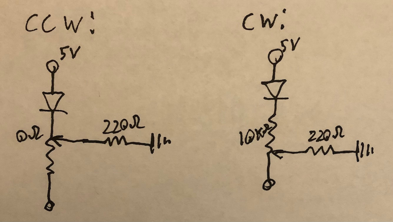
Within P5.JS, I first start by creating a 500X500 gradient as the background (using code adapted from here), and drawing the "CW" and "CCW" text with the line down the middle. Then I made a variable to control direction called "cwOrccw" which I set to o if the mouse's x position was > 250 and 1 if not. I also made the speed variable "speedOut" which maps the mouse's y position between 0 and 500 to a value between 1023 and 0 (as this is the value the Arduino is expecting). I sent these values to the Arduino using "serial.write()", separating them with ",", and ending the line with "\n". See below for a video of the sketch in action! See here for the sketch.
Within P5.JS, I first start by creating a 500X500 gradient as the background (using code adapted from here), and drawing the "CW" and "CCW" text with the line down the middle. Then I made a variable to control direction called "cwOrccw" which I set to o if the mouse's x position was > 250 and 1 if not. I also made the speed variable "speedOut" which maps the mouse's y position between 0 and 500 to a value between 1023 and 0 (as this is the value the Arduino is expecting). I sent these values to the Arduino using "serial.write()", separating them with ",", and ending the line with "\n". See below for a video of the sketch in action! See here for the sketch.
Final Project: playtesting
BiSignals
BiSginals elevates the safety and enjoyment for those sharing the road with bicycles. We do so with creative animations displayed on a seat post mounted LED grid housing which displays animations controlled by a switch, flex sensor, and accelerometer.
E.O. Rafelson: LED Grid animations, LED Circuit
Kaj Harvey: Soldering, Flex Senor circuit, Switch circuit
Me: Enclosure fabrication, Sensor mounting, Accelerometer Circuit
E.O. Rafelson: LED Grid animations, LED Circuit
Kaj Harvey: Soldering, Flex Senor circuit, Switch circuit
Me: Enclosure fabrication, Sensor mounting, Accelerometer Circuit
My contributions so far:
So far I have procured the bike, enclosure, mounting bracket, 3-position switch, insulated wire, and the accelerometer and have began arranging the sensors on the bike and mounting the enclosure. I also wrote code for integrating the sensors to change the animations.
Final Project: Final
BiSignals


BiSginals elevates the safety and enjoyment for those sharing the road with bicycles. We do so with creative animations displayed on a seat post mounted LED grid housing which displays animations controlled by a 3 position switch, micro switch, and accelerometer.
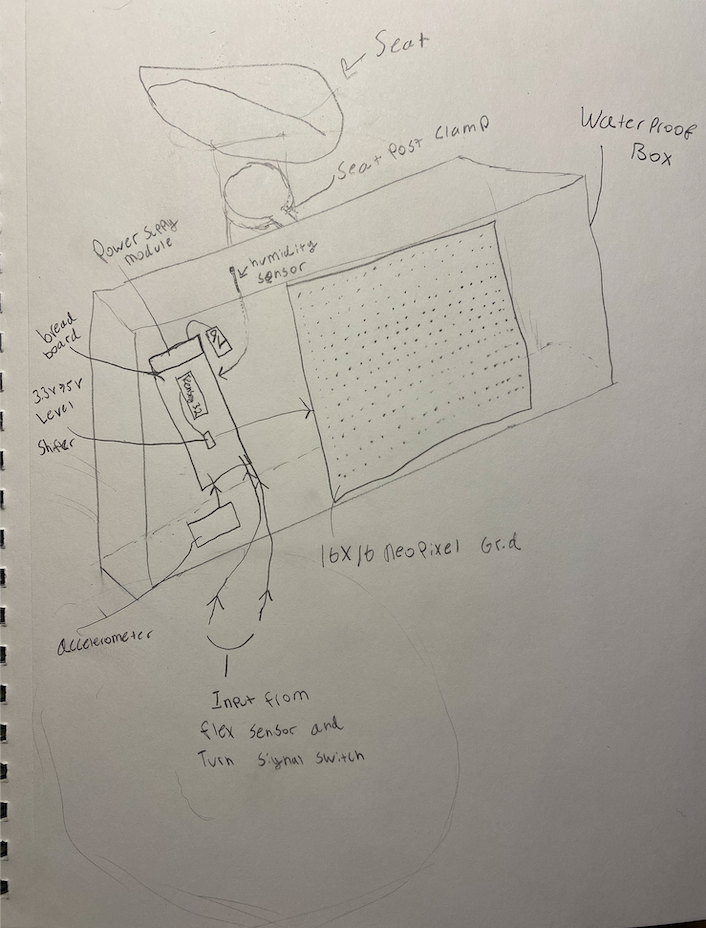
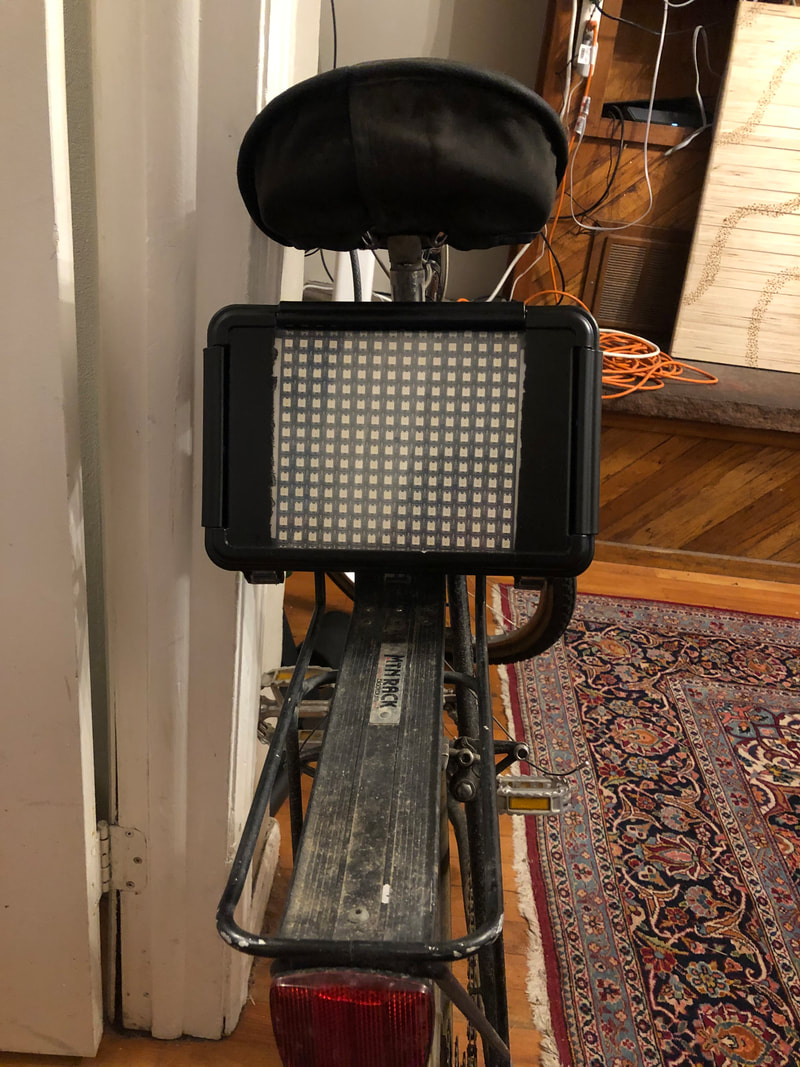
The BiSignals has 3 major components (Enclosure, Sensor Circuit, LED Circuit):
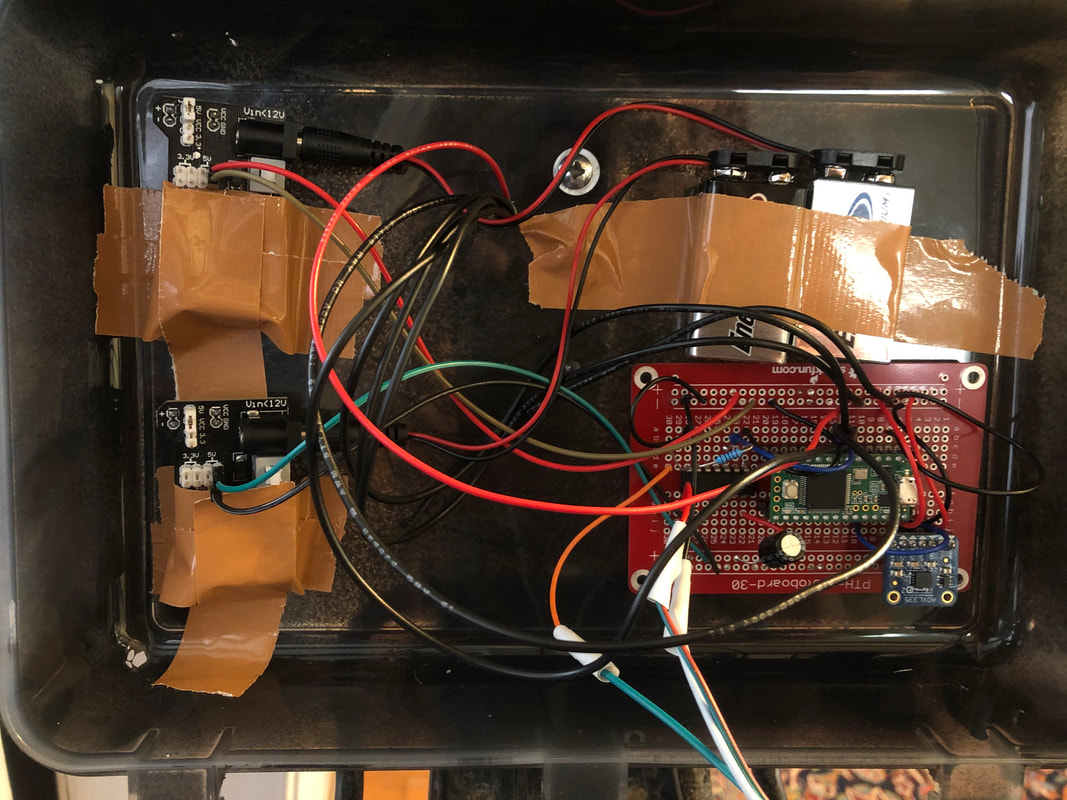
The enclosure is fabricated from a waterproof Tupperware container. It is spray painted with a black rubberized coating to make it look more finished and provide more durability. on the inside, the components are secured with heavy duty tape and Velcro. A seat post bracket is mounted to the back of the enclosure with screws so it can sit securely behind the seat. A small hole is drilled in the back to allow for the sensor wires to enter the enclosure while keeping the enclosure water tight.
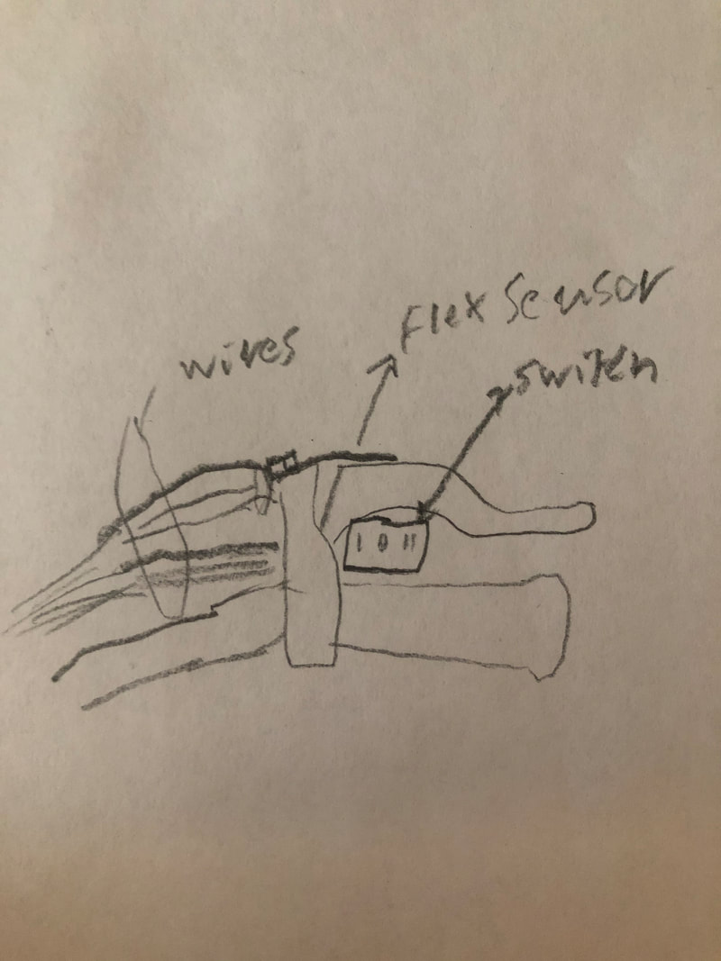
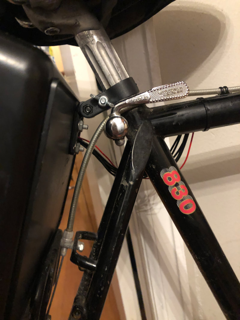
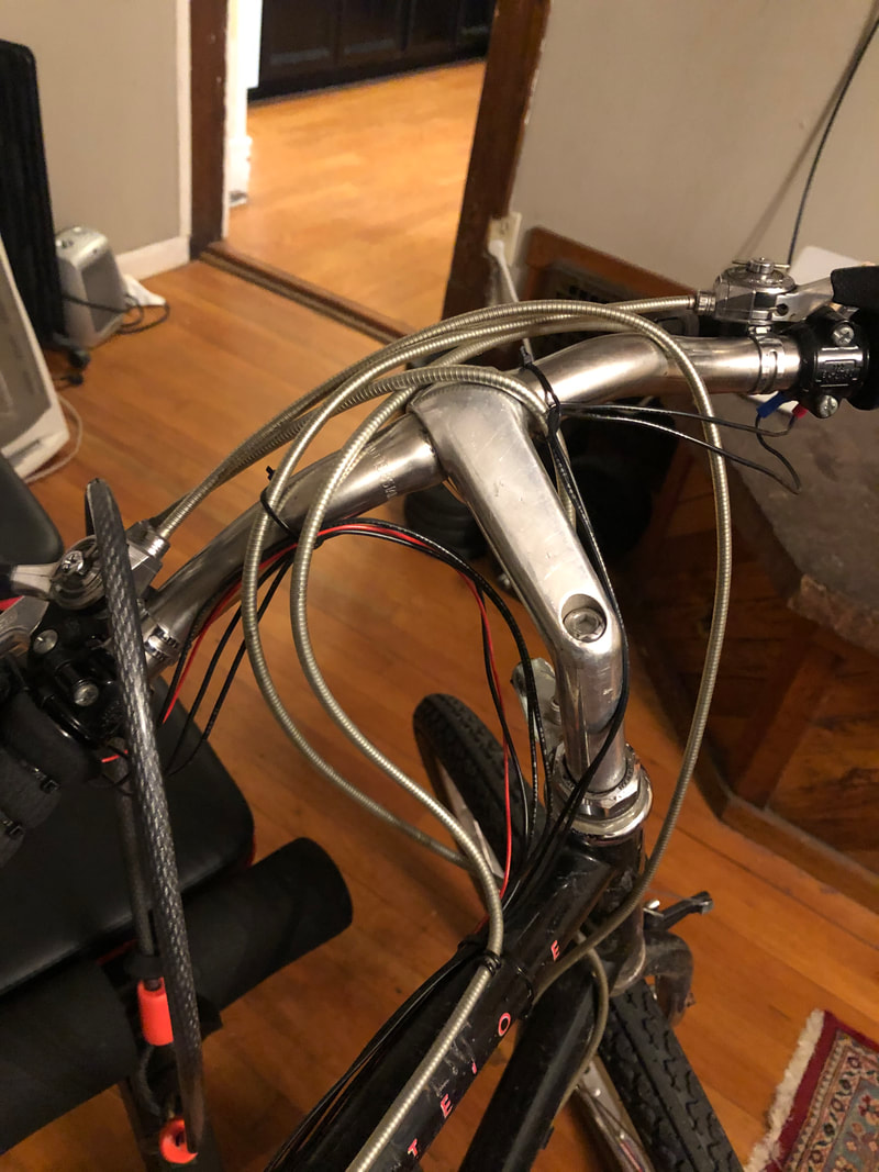
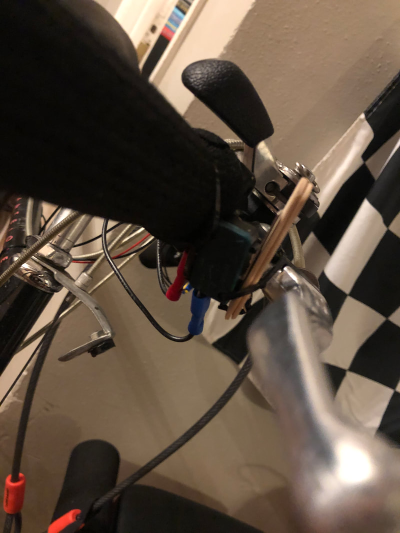
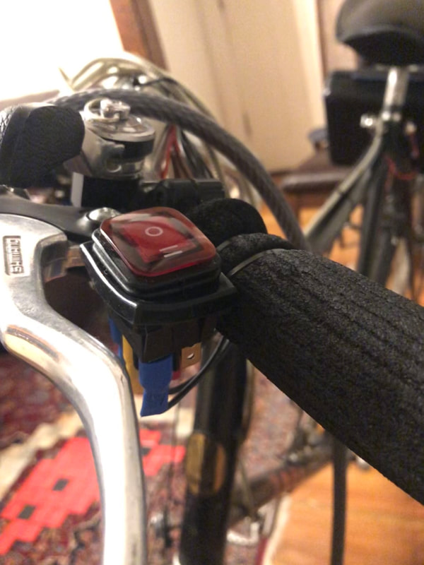
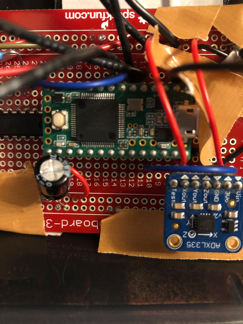
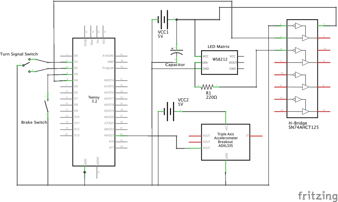
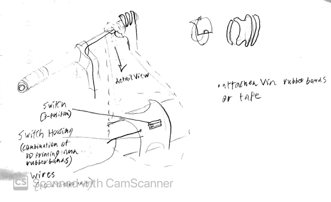
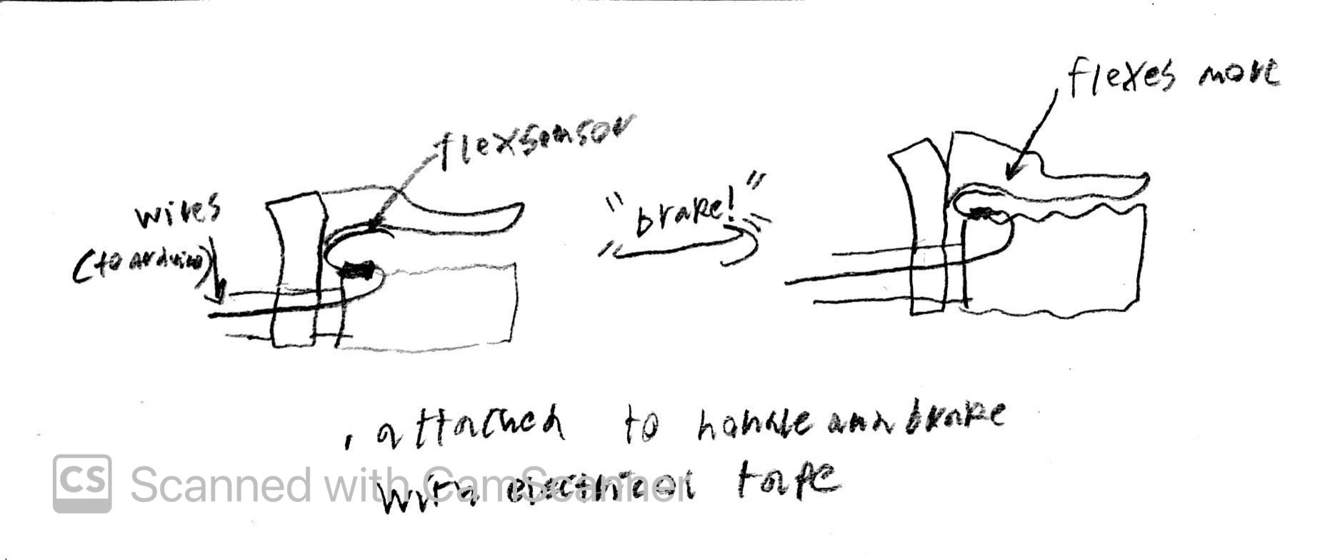
The Sensor Circuit is comprised of 3 sensors which connect to the Arduino. The first is the brake sensor which is made of a micro switch. It is positioned so that the switch is flipped when you squeeze the brake, and is sense by the Arduino via an input pull up resistor. The second is the turn signal switch. It is positioned on the left side handle in between the brake and the handle (It actually fits perfectly without interference). When you flip it to either side it is sensed by the Arduino via an input pull up resistor. The third is the accelerometer. This is mounted on the board and sends an analog signal to the Arduino, this signal changes depending on the acceleration of the bike.
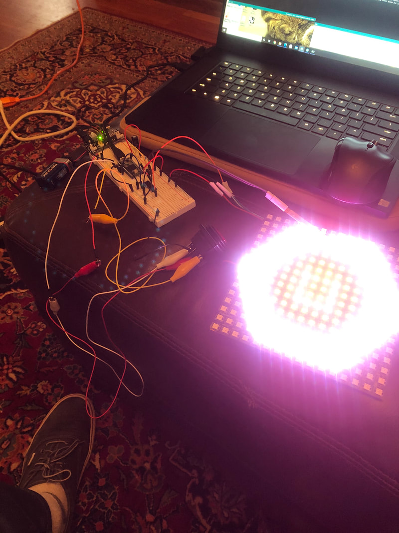
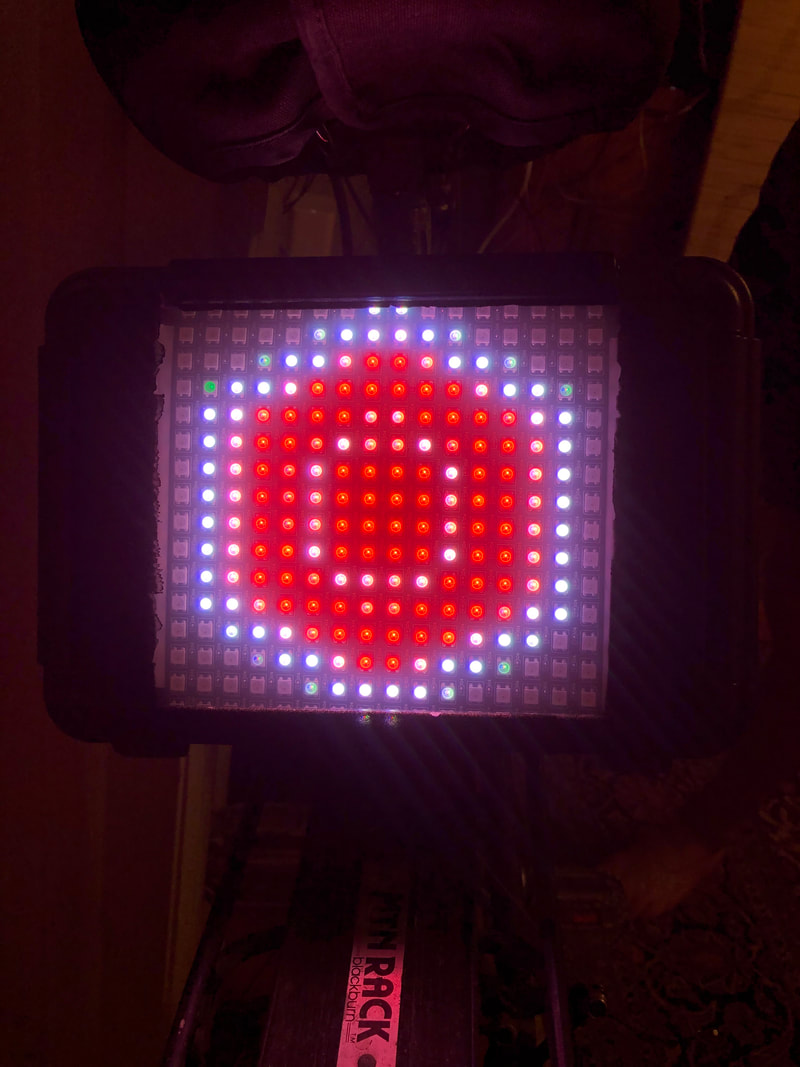
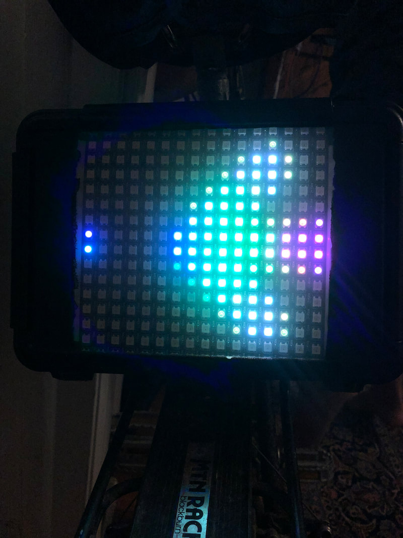
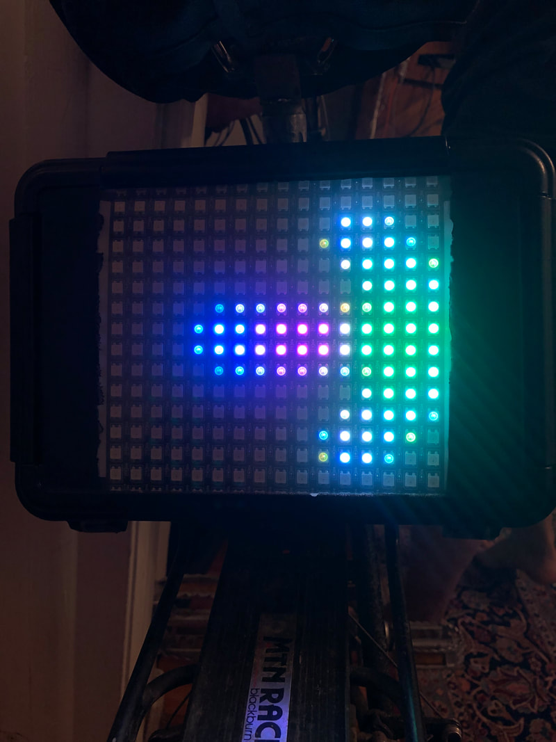
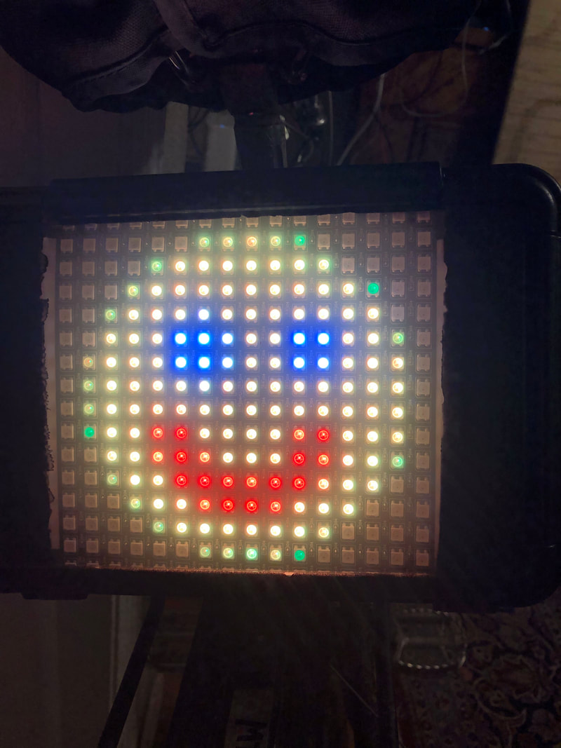
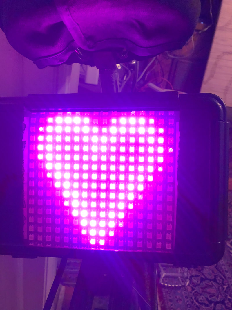
The LED Circuit is comprised of the Led matrix and an H-bridge. The animations were made by creating gifs in After Effects and then converting them into frames readable by the LED matrix using Processing 2.2.1 (we used code and tutorial from here). The animations are triggered by the sensor code and displayed via the "DIN" wire to the grid. When we get a sensor reading from any of our sensors, we display the corresponding animation. Turn signals take precedent over the stop signal, and the stop signal takes precedent over the bump animation.
The process to get to the final product Is outline in the "playtesting" post. See below for drawings throughout our design process and photos of us testing the circuit along the way. See above for our video of our working final product (made by E.O.) and photos of individual animations and components.
The BiSignals has 3 major components (Enclosure, Sensor Circuit, LED Circuit):
The enclosure is fabricated from a waterproof Tupperware container. It is spray painted with a black rubberized coating to make it look more finished and provide more durability. on the inside, the components are secured with heavy duty tape and Velcro. A seat post bracket is mounted to the back of the enclosure with screws so it can sit securely behind the seat. A small hole is drilled in the back to allow for the sensor wires to enter the enclosure while keeping the enclosure water tight.
The Sensor Circuit is comprised of 3 sensors which connect to the Arduino. The first is the brake sensor which is made of a micro switch. It is positioned so that the switch is flipped when you squeeze the brake, and is sense by the Arduino via an input pull up resistor. The second is the turn signal switch. It is positioned on the left side handle in between the brake and the handle (It actually fits perfectly without interference). When you flip it to either side it is sensed by the Arduino via an input pull up resistor. The third is the accelerometer. This is mounted on the board and sends an analog signal to the Arduino, this signal changes depending on the acceleration of the bike.
The LED Circuit is comprised of the Led matrix and an H-bridge. The animations were made by creating gifs in After Effects and then converting them into frames readable by the LED matrix using Processing 2.2.1 (we used code and tutorial from here). The animations are triggered by the sensor code and displayed via the "DIN" wire to the grid. When we get a sensor reading from any of our sensors, we display the corresponding animation. Turn signals take precedent over the stop signal, and the stop signal takes precedent over the bump animation.
The process to get to the final product Is outline in the "playtesting" post. See below for drawings throughout our design process and photos of us testing the circuit along the way. See above for our video of our working final product (made by E.O.) and photos of individual animations and components.
Some areas for improvement could be with the circuit. A lot of our wires were not strong enough and kept breaking. This caused our circuit to fail at times while riding. A fix to this could be better wires, but could also be to add foam to the inside of the container to minimize component movement. We also noticed that the LED grid drained our battery very quickly. We could probably fix this with a better battery pack than the 5V converter given in our kit. Another room for improvement could be the brake switch. While it works, it is somewhat crude and could look more finished if we created a custom enclosure for the switch as well.
Credits:
E.O. Rafelson: LED Grid Animations, LED Circuit, Sensor Mounting, Video Production, Animation Code
Kaj Harvey: Soldering, Brake Switch Circuit, Switch Circuit, Schematic Drawing, Switch Code,
Me: Enclosure fabrication, Enclosure Finishing, Sensor Mounting, Accelerometer Circuit, Soldering, Integration Code
Kaj Harvey: Soldering, Brake Switch Circuit, Switch Circuit, Schematic Drawing, Switch Code,
Me: Enclosure fabrication, Enclosure Finishing, Sensor Mounting, Accelerometer Circuit, Soldering, Integration Code
Individual Summary:
My contributions have been the following: I procured the bike, enclosure, mounting bracket, 3-position switch, insulated wire, and the accelerometer. I mounted the bracket to the enclosure, finished the enclosure with a black rubberized coating, helped to solder our circuit to the final protoboard, and aided in troubleshooting the final product. I also mounted the switched with E.O., and added the extra wood piece to make the brake switch function properly. I also wrote code for integrating the sensors to change the animations.
